5P32E Ch= HS-559
Motorola Inc. (ex Galvin Mfg.Co. Chicago); Schaumburg (IL)
- Land
- USA
- Hersteller / Marke
- Motorola Inc. (ex Galvin Mfg.Co. Chicago); Schaumburg (IL)
- Jahr
- 1957 ?
- Kategorie
- Rundfunkempfänger (Radio - oder Tuner nach WW2)
- Radiomuseum.org ID
- 84374


Ebay Nr. 220070309226 Bild bearbeitet.
Ebay Nr. 220070309226 Bild bearbeitet.
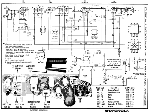
Klicken Sie auf den Schaltplanausschnitt, um diesen kostenlos als Dokument anzufordern.
- Anzahl Röhren
- 4
- Hauptprinzip
- Superhet allgemein; ZF/IF 455 kHz; 2 NF-Stufe(n)
- Anzahl Kreise
- 6 Kreis(e) AM
- Wellenbereiche
- Mittelwelle, keine anderen.
- Betriebsart / Volt
- Netz- / Batteriespeisung / (7.5; 90); AC/DC 117 Volt
- Lautsprecher
- Dynamischer LS, keine Erregerspule (permanentdynamisch) / Ø 4 inch = 10.2 cm
- Material
- Plastikgehäuse (nicht Bakelit), Thermoplast
- von Radiomuseum.org
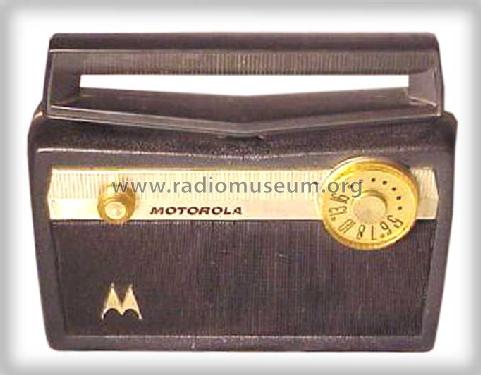
- Modell: 5P32E Ch= HS-559 - Motorola Inc. ex Galvin Mfg.Co
- Form
- Reisegerät > 20 cm (netzunabhängig betreibbar)
- Bemerkung
-
Color= Navy leatherette. See here about Tinkertoy technique. The Beitman R-18 shows the following models with this chassis HS-559: 5P31A, 5P32C, 5P32E, 5P32R and 5P32Y but also 5P33EW, 5P33VW and 5P33W for chassis HS-561. See also 66L1 and 66L2 with Tinkertoy technique.
- Schaltungsnachweis
- Beitman Radio Diagrams Vol. 18, 1958
- Literaturnachweis
- Collector's Guide to Antique Radios (6th edition)
- Literatur/Schema (1)
- Photofact Folder, Howard W. SAMS (Set 363 Folder 14 Dated 7-57)
- Autor
- Modellseite von Egon Penker angelegt. Siehe bei "Änderungsvorschlag" für weitere Mitarbeit.
- Weitere Modelle
-
Hier finden Sie 4655 Modelle, davon 2982 mit Bildern und 4154 mit Schaltbildern.
Alle gelisteten Radios usw. von Motorola Inc. (ex Galvin Mfg.Co. Chicago); Schaumburg (IL)
Forumsbeiträge zum Modell: Motorola Inc. ex: 5P32E Ch= HS-559
Threads: 1 | Posts: 1
Fellow Radiophiles,
As I was organizing some battery tubes in my replacement stock, I came across the 1DN5.
This is a very unusual remote cut-off Audio pentode for use in AC/DC portable radios that use a 50mA filament series string. There is also an additional anode near the negative end of the filament to serve as the diode detector.
Our database shows two Motorola AC/DC portable chassis that use this tube for the same purpose: HS-559 and HS-647.
The filaments of the 4 tubes in the radio are wired in series starting from ground:
1R5 pentagrid converter
1DN5 Detector, AVC, Audio preamp
1U4 IF pentode
3V4 audio power
The voltage at the top of the 50mA filamentary string is 7.5VDC, which may come for the A battery, or from a high power 2K resistor tied the +95V, which dissipates about 5W when the radio is under AC power.
The 1DN5 is the audio preamp, but with the AVC voltage applied to the control grid as it's source of bias. The gain of the audio preamp depends on the strength of the station. Strong stations will produce an AVC voltage that reduces the 1DN5 gain.
Just as unusual, there is no AVC applied to the IF pentode 1U4. The control grid of this tube is fixed-biased about 1.5V below the negative end of it's filamentary cathode.
Finally, the 1R5 pentagrid converter tube get's it's RF grid bias via 3.3Meg from the AVC voltage that is developed by the detector anode inside the 1DN5. But this detector diode sits 1.5V higher than usual, because it's cathode is the second filament in the string. This added +1.5V serves as what is known as "AVC delay". This means that the 1R5 will not start having it's gain reduced until at least -1.5V of incomming carrier overcomes the +1.5V "AVC delay".
The AVC voltage that appears at the RF input grid of the 1R5 is also applied directly to the remote cutoff grid of the audio pentode in the 1DN5. Keep in mind that it's cathode is second-up in the filamentary string, so with zero input signal, the AVC voltage appears at the 1DN5 remote cutoff grid as a -1.5V bias. As signals are tuned-in that produce more than -1.5V of detected carrier, then the grid of the 1R5 pentagrid converter and the remote-cutoff grid of the 1DN5 audio pentode will go negative together to attenuate the volume.
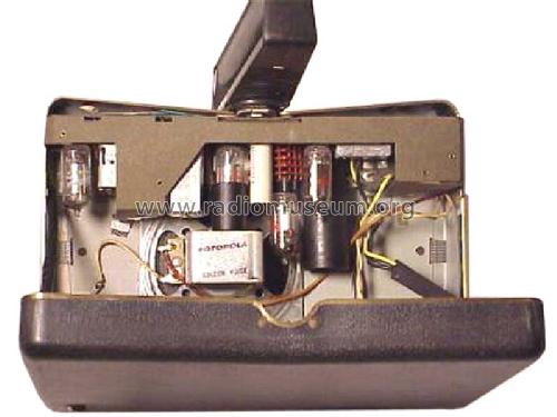
One last peculiarity is that the 1DN5 is mounted on a Tinker-Toy module, which contains most of the resistors and capacitors in the radio.
Summarizing, the AVC voltage is applied in the usual negative Feedback fashion to the 1R5 pentagrid converter, but is applied in Feedforward to the 1DN5 audio preamp.
Why all this strange grid bias and AVC complication? It saves the cost of a power transformer. Without a power transformer, the least inneficient way to drive the DC filaments is as a series string drawing 50mA. The series string keeps the dissipation in the 2k filament ballast resistor at only 5W. If all filaments were wired in parallel, the ballast resistor would have to supply 250mA and dissipate 20W.
Regards,
-Joe
The correct reference for one Motorola radio is HS-559, not HS-599.
-Joe
Joe Sousa, 28.Aug.10