Surcouf avec cadre - EM80
Océanic, ITT Océanic; Paris
- Pays
- France
- Fabricant / Marque
- Océanic, ITT Océanic; Paris
- Année
- 1956 ?
- Catégorie
- Radio - ou tuner d'après la guerre 1939-45
- Radiomuseum.org ID
- 98964
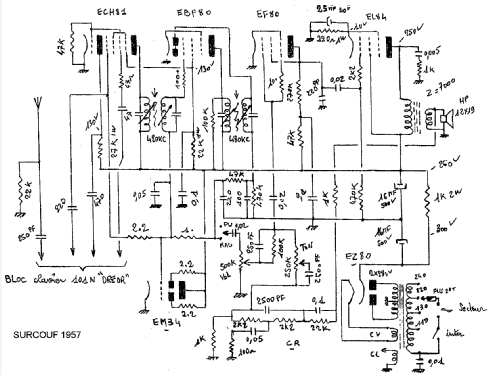


Cliquez sur la vignette du schéma pour le demander en tant que document gratuit.
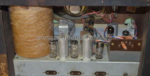
- No. de tubes
- 6
- Principe général
- Super hétérodyne (en général)
- Gammes d'ondes
- PO, GO et 2 x OC
- Tension / type courant
- Alimentation Courant Alternatif (CA) / 110-240 Volt
- Haut-parleur
- HP dynamique oval à aimant permanent
- Matière
- Boitier en bois
- De Radiomuseum.org
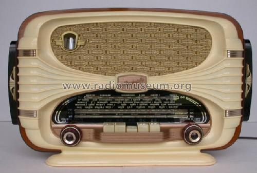
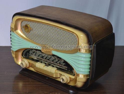
- Modèle: Surcouf [avec cadre - EM80] - Océanic, ITT Océanic; Paris
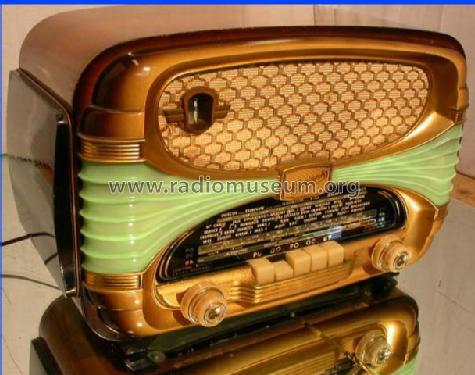
- Forme
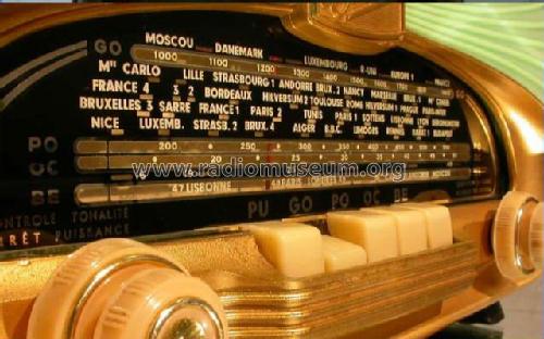
- Modèle de table avec boutons poussoirs.
- Dimensions (LHP)
- 20 x 12.5 x 10 inch / 508 x 318 x 254 mm
- Remarques
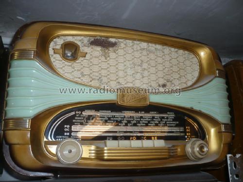
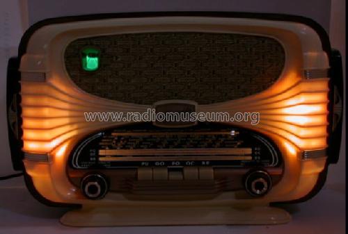
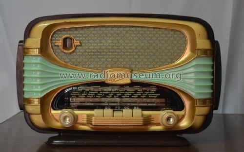
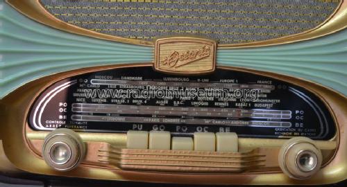
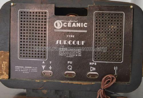
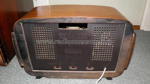
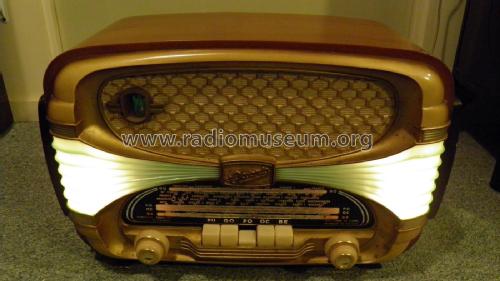
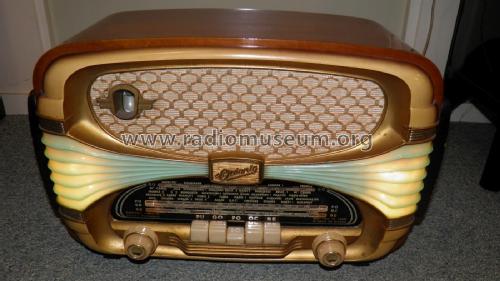
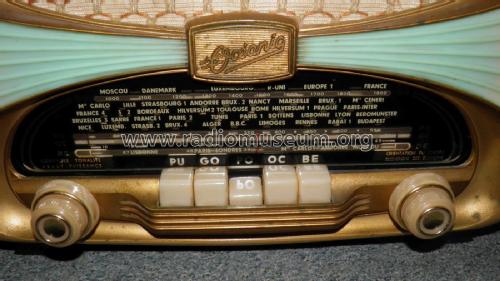
- Océanic Surcouf;
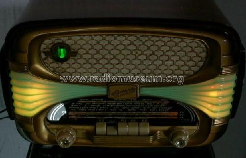
Blue and gold colored front panel, unique illuminated,
LW, MW, BE - Bande étalée: ~47 - 50 m,
SW: ~16 - 49 m band,
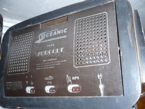
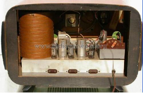
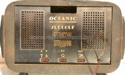
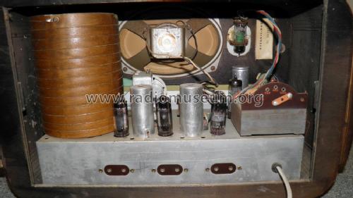
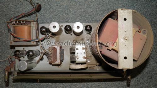
tone control, built in antenna coil, tuning indicator tube, terminals for phono-in, ext. speaker & antenna/earth. The surcouf has a built in shielded antenna - see the cylinder on the left.
- Auteur
- Modèle crée par Gottfried Silberhorn. Voir les propositions de modification pour les contributeurs supplémentaires.
- D'autres Modèles
-
Vous pourrez trouver sous ce lien 159 modèles d'appareils, 134 avec des images et 40 avec des schémas.
Tous les appareils de Océanic, ITT Océanic; Paris
Collections
Le modèle Surcouf fait partie des collections des membres suivants.
Contributions du forum pour ce modèle: Océanic, ITT Océanic: Surcouf
Discussions: 3 | Publications: 6
Radio enthusiasts, how does the vertical loop antenna drum work in the Oceanic Surcouf?
Every AM loop antenna I have ever seen always had a horizontally oriented axis.
The reason for this is that AM transmitters generally transmit with a vertical mast, which polarizes the magnetic field into horizontal magnetic field line circles.
I can't help but wonder if French transmitters used a different polarization, perhaps with some other benefit that I am not aware of, like lower noise, better imunity from fading, or rejection of stations with a conventional polarization.
What bands is the drum for?
Regards,
-Joe
Joe Sousa, 16.Jul.09
Norbert Haselbach, 13.Mar.07
Norbert Haselbach, 13.Mar.07