- Land
- Argentinien
- Hersteller / Marke
- Philips Argentina, FAPESA, Miniwatt tubes; Buenos Aires
- Jahr
- 1937/1938 ?
- Kategorie
- Rundfunkempfänger (Radio - oder Tuner nach WW2)
- Radiomuseum.org ID
- 89268
restored by Jorge Mochkovsky


- Anzahl Röhren
- 5
- Hauptprinzip
- Superhet allgemein; ZF/IF 475 kHz
- Wellenbereiche
- Mittelwelle und Kurzwelle.
- Betriebsart / Volt
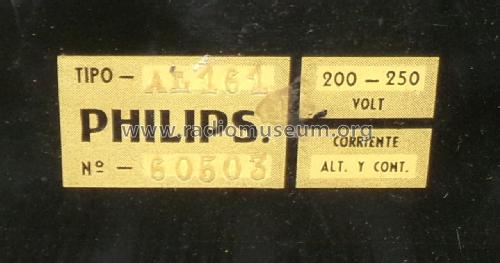
- Allstromgerät / 200-250 Volt
- Lautsprecher
- Dynamischer LS, keine Erregerspule (permanentdynamisch) / Ø 6 inch = 15.2 cm
- Material
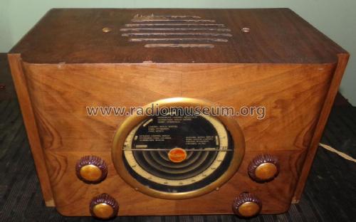
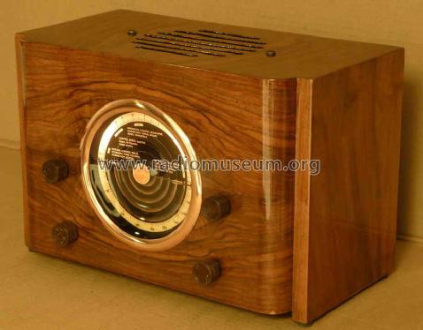
- Gerät mit Holzgehäuse
- von Radiomuseum.org
- Modell: AL161 - Philips Argentina, FAPESA,
- Form
- Tischgerät ohne Drucktasten, bis 35 cm Breite (Kleingerät, meist dekorativ. Nur für Netzbetrieb, doch Transportgriff möglich).
- Abmessungen (BHT)
- 15 x 10 x 8.5 inch / 381 x 254 x 216 mm
- Bemerkung
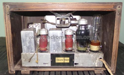
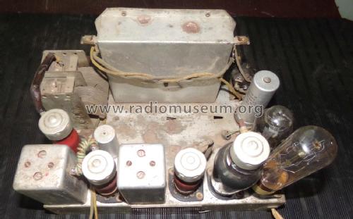
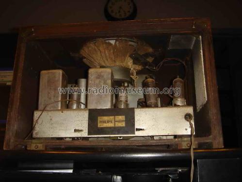
- The radio has 6 bases for the European P8A tubes - 5 of which are receiving tubes; and the C1 or C10 regulator tube. In some locations in Argentina, the power available may have been 110-120volts AC. Per early research by myself; and referenced recently by member Juan Carlos Franco.
- Nettogewicht
- 6 kg / 13 lb 3.5 oz (13.216 lb)
- Autor
- Modellseite von Robert Sarbell † 22.3.22 angelegt. Siehe bei "Änderungsvorschlag" für weitere Mitarbeit.
- Weitere Modelle
-
Hier finden Sie 278 Modelle, davon 173 mit Bildern und 199 mit Schaltbildern.
Alle gelisteten Radios usw. von Philips Argentina, FAPESA, Miniwatt tubes; Buenos Aires
Sammlungen
Das Modell befindet sich in den Sammlungen folgender Mitglieder.
Forumsbeiträge zum Modell: Philips Argentina,: AL161
Threads: 2 | Posts: 23
About this article,
http://www.radiomuseum.org/forum/philips_al161_mini_chairside_radio_200_250v_acdc.html
Mr. António Manuel Rodrigues dos Santos would like to add more information about.
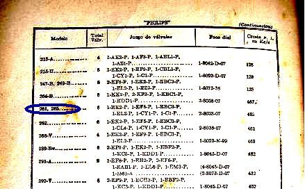
He notice that in the same Philips manual, AL261 and AL265, have the same group of tubes.
Regards
Mário Coelho
http://www.radiomuseum.org/forum/philips_al161_mini_chairside_radio_200_250v_acdc.html
Mr. António Manuel Rodrigues dos Santos would like to add more information about.
He notice that in the same Philips manual, AL261 and AL265, have the same group of tubes.
Regards
Mário Coelho
Mario Coelho, 19.Apr.06
Dear radiomuseum friends,
I have been researching for the last 7 weeks,, unsuccessfully to determine the original tube configuration and background for this unusual small wooden cabinet table radio that I bought from a gentleman in Argentina.
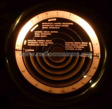
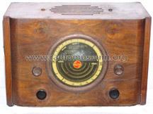
The dial has 2 wave bands ONDA CORTA (from 5.7 to 16.8 MC); and
ONDA LARGA (from 535 to 1450KC). The 2 small upper knobs have
the Philips logo embossed on them. The larger dark brown knobs may
or may not be original.
Note that the speaker faces toward the top of the cabinet, and there is
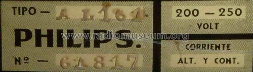
a small sheet of asbestos on the right side near the current regulator
socket. The ID plate is made of a plastic material and is enlarged below.
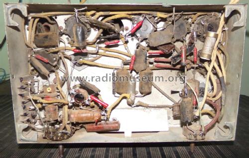
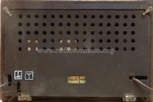
Obviously the rear panel would have been of great importance, since this
little radio operates with the "hot chassis". . . . . making it quite dangerous
to operate without securing the openings. Even the mountings for the
chassis to the cabinet verify this.
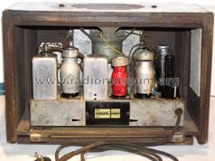
When I received the radio from the seller in Argentina, someone had
placed a 6C6 tube within the early European octal side-pin socket
located between IFT1 and IFT2. All 5 tube sockets are the European
octal side-pin, and the current regulator socket is the typical 4-pin.
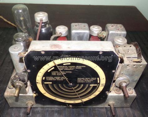
Several components either on top of the chassis, or the bottom identify a
manufacturer from the United States. The markings on the capacitors appear to have been "darkened out". The red cylindrical resistors I am familiar with - some
have the ratings identified with an apparent date code, and the 6
smaller ones are marked 59. and a small triangle. The tube filaments
are definitely in series - the continuity check (with small jumpers attached
to pins 2-3) confirms this.
I have MANY MANY notes and additional observations, but have
not had a Philips radio collector provide any additional assistance.
My best analysis of the tube configuration and layout is as follows:
CK1, CF3, CBC1, CL4, CY1, and the C8 regulator - the layout
closely resembles a Philips 461U or 461HU or a derivative of the
Philips Gavotta model 272HU.
I would be most appreciative for any assistance, and add in closing
that there are a few other unusual observations. I posted an item
to the Netherlands Oude Radio forum in early October, and have
received NO replies yet.
I apologize for not correcting the above statement since I received the response from Mr Henk Kremer from the Netherlands Oude radio forum on 22 Nov - in which he stated the most likely tube configuration
. . . . . ."De buizenbezetting lijkt mij CK1-CF3-CBC1-CBL1-CY1 en een stroomregelbuis met pennen,zie ookhet plaa
Henk Kramer 22. Nov 2005 18:29:00
Respectfully,
Robert Sarbell
I have been researching for the last 7 weeks,, unsuccessfully to determine the original tube configuration and background for this unusual small wooden cabinet table radio that I bought from a gentleman in Argentina.
The dial has 2 wave bands ONDA CORTA (from 5.7 to 16.8 MC); and
ONDA LARGA (from 535 to 1450KC). The 2 small upper knobs have
the Philips logo embossed on them. The larger dark brown knobs may
or may not be original.
Note that the speaker faces toward the top of the cabinet, and there is
a small sheet of asbestos on the right side near the current regulator
socket. The ID plate is made of a plastic material and is enlarged below.
Obviously the rear panel would have been of great importance, since this
little radio operates with the "hot chassis". . . . . making it quite dangerous
to operate without securing the openings. Even the mountings for the
chassis to the cabinet verify this.
When I received the radio from the seller in Argentina, someone had
placed a 6C6 tube within the early European octal side-pin socket
located between IFT1 and IFT2. All 5 tube sockets are the European
octal side-pin, and the current regulator socket is the typical 4-pin.
Several components either on top of the chassis, or the bottom identify a
manufacturer from the United States. The markings on the capacitors appear to have been "darkened out". The red cylindrical resistors I am familiar with - some
have the ratings identified with an apparent date code, and the 6
smaller ones are marked 59. and a small triangle. The tube filaments
are definitely in series - the continuity check (with small jumpers attached
to pins 2-3) confirms this.
I have MANY MANY notes and additional observations, but have
not had a Philips radio collector provide any additional assistance.
My best analysis of the tube configuration and layout is as follows:
CK1, CF3, CBC1, CL4, CY1, and the C8 regulator - the layout
closely resembles a Philips 461U or 461HU or a derivative of the
Philips Gavotta model 272HU.
I would be most appreciative for any assistance, and add in closing
that there are a few other unusual observations. I posted an item
to the Netherlands Oude Radio forum in early October, and have
received NO replies yet.
I apologize for not correcting the above statement since I received the response from Mr Henk Kremer from the Netherlands Oude radio forum on 22 Nov - in which he stated the most likely tube configuration
. . . . . ."De buizenbezetting lijkt mij CK1-CF3-CBC1-CBL1-CY1 en een stroomregelbuis met pennen,zie ookhet plaa
Henk Kramer 22. Nov 2005 18:29:00
Respectfully,
Robert Sarbell
Anlagen
- Front view (98 KB)
- Rear (106 KB)
- Chassis (123 KB)
- Underside (141 KB)
- ID Plate (89 KB)
Robert Sarbell † 22.3.22, 19.Nov.05