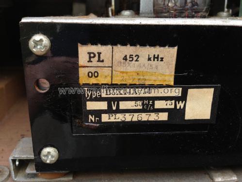
Bi-Ampli B5X14A /54
Philips Belgium (Belgien)
- Country
- Belgium
- Manufacturer / Brand
- Philips Belgium (Belgien)
- Year
- 1961 ?
- Category
- Broadcast Receiver - or past WW2 Tuner
- Radiomuseum.org ID
- 225015


- Number of Tubes
- 10
- Main principle
- Superheterodyne (common); ZF/IF 452/10700 kHz; 2 AF stage(s)
- Wave bands
- Broadcast, Long Wave, Short Wave plus FM or UHF.
- Power type and voltage
- Alternating Current supply (AC) / 110-245 Volt
- Loudspeaker
- 2 Loudspeakers / Ø 6.7 inch = 17 cm
- Material
- Wooden case
- from Radiomuseum.org
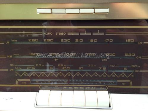
- Model: Bi-Ampli B5X14A /54 - Philips Belgium Belgien
- Shape
- Tablemodel with Push Buttons.
- Dimensions (WHD)
- 21.75 x 9.5 x 9.25 inch / 552 x 241 x 235 mm
- Notes
-
Philips B5X14A/54 is an export model for the North American market, FM Band 88 to 108 MHz.
800 ohm loudspeakers. BC dial has C-D marks (Civil Defense frequencies).
- Net weight (2.2 lb = 1 kg)
- 20 lb 4 oz (20.25 lb) / 9.194 kg
- Author
- Model page created by David Schulman. See "Data change" for further contributors.
- Other Models
-
Here you find 601 models, 577 with images and 347 with schematics for wireless sets etc. In French: TSF for Télégraphie sans fil.
All listed radios etc. from Philips Belgium (Belgien)
Collections
The model Bi-Ampli is part of the collections of the following members.
Forum contributions about this model: Philips Belgium: Bi-Ampli B5X14A /54
Threads: 1 | Posts: 2
This weekend, I finally decided to fix my Norelco's pilot problem. It seems that Z80D4/81 pilot bulbs and myself have never been in the same place. Taking heart from another article on this marvelous web site, I set to bring light to the aged radio.
Here in the USA, I located a source (MPJA.com) that offered clear 10000 mcp LEDs for a reasonalble rate. Once these were in hand. Norelco and I went to the Shop-
It had been a while since I'd overhauled the power supply and controls on this one, so we had to get re-acquainted.... Remember, these chassis come out from the FRONT of the radio, once you take the molding off around the keyboard. Then, you're all ready to go!
The two pilot bulb sockets are mounted on a small piece of aluminum, that screws to the main chassis. Once the one screw is removed, you can pull the bulb sockets out from behind the dial.
As these LEDs were rated at 20ma, and the feed was 6.3 volts, I selected a pair of 330 ohm resistors to drop the current/voltage. I soldered one of these to the cathode legs of 2 of the LEDs, about a quarter inch from the LED base. A wrap of 3/4 inch electrical tape around the cathode leg/solder joint/resistor was made to prevent any shorts.
Mounting the LEDs was a very good experience, as the bottom contact of the pilot bulb socket is a hollow tube. 'Straddling' the pilot bulb socket with the LED leads, the resistor went inside the socket and the LED anode lead stayed outside the socket wall. The resistor leg ran thru the hollow base of the socket, and soldered neatly to the supply wire. Solder the anode leg of the LED to the ground wire lug on the outside of the socket, and the connections are complete.
Re-mount the pilot bulb chassis, and apply power to check for proper operation. Put it all back together again, and you won't have to look for your flashlight to tune the radio any more!
Attachments
Bruce Jones, 23.Jan.14