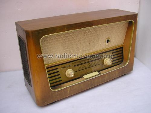
Sekretär III 697/75GWU 3D
Stern-Radio Sonneberg, VEB, RFT; SONRA; -vorm.: EAK (Ostd.) - ex. AEG
- País
- Alemania
- Fabricante / Marca
- Stern-Radio Sonneberg, VEB, RFT; SONRA; -vorm.: EAK (Ostd.) - ex. AEG
- Año
- 1960 ??
- Categoría
- Radio - o Sintonizador pasado WW2
- Radiomuseum.org ID
- 126147

D_RFT_Sekretär III 667/75GWU 3D

D_RFT_Sekretär III 697/75GWU 3D_innen
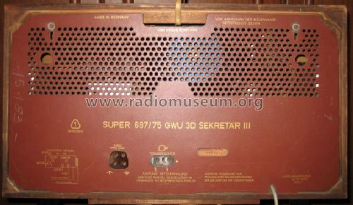
D_RFT-Sekretär iii 697/75GWU 3D_Rueckwand
- Numero de valvulas
- 6
- Numero de transistores
- Semiconductores
- Tr.Gl.=Metal-rectif.
- Principio principal
- Superheterodino en general; ZF/IF 473/10700 kHz
- Número de circuitos sintonía
- 6 Circuíto(s) AM 9 Circuíto(s) FM
- Gama de ondas
- OM, OL y FM
- Tensión de funcionamiento
- Red: Aparato AC/DC. / 220 Volt
- Altavoz
- 3 Altavoces / Ø 22 cm = 8.7 inch
- Potencia de salida
- 2 W (unknown quality)
- Material
- Madera
- de Radiomuseum.org
- Modelo: Sekretär III 697/75GWU 3D - Stern-Radio Sonneberg, VEB,
- Forma
- Sobremesa de cualquier forma, detalles no conocidos.
- Ancho, altura, profundidad
- 560 x 315 x 185 mm / 22 x 12.4 x 7.3 inch
- Anotaciones
- TA nur mit Trenntrafo möglich.
- Peso neto
- 7 kg / 15 lb 6.7 oz (15.419 lb)
- Procedencia de los datos
- - - Data from my own collection
- Autor
- Modelo creado por Klemens Rhode. Ver en "Modificar Ficha" los participantes posteriores.
- Otros modelos
-
Donde encontrará 386 modelos, 313 con imágenes y 288 con esquemas.
Ir al listado general de Stern-Radio Sonneberg, VEB, RFT; SONRA; -vorm.: EAK (Ostd.) - ex. AEG
Colecciones
El modelo Sekretär III es parte de las colecciones de los siguientes miembros.
Contribuciones en el Foro acerca de este modelo: Stern-Radio: Sekretär III 697/75GWU 3D
Hilos: 1 | Mensajes: 3
I'm restoring a Sekretär III 697/75GWU 3D radio. There wasn't a schematic for this model in RMorg but I used a schematic for model Sekretär III 697/62GWU which I believe to be close enough. There are no component values in the schematic and I need to know the value of one resistor. It is burned open and the markings are no longer visible. I think it is R11 in the schematic (in the lower left corner, antenna circuit). I have no idea how it got burned. There is no visible damage in the other components.
Also I removed the 50 + 100 uF electrolytic capacitor can but I forgot to look which one is the first and which one is the second filter. I'm guessing that the 100 uF is the first. Am I right?
The final question is about the half wave selenium rectifier. I measured its resistance with a digital ohm meter and I got 1.3 megaohms in the other direction and 1.6 megaohms in the other. I assume that it is bad?
All answers will be greatly appreciated.
Timo
Timo Haveri, 16.Jun.08