ora: ORADYNE S536 and L636, the unequal twins
ora: ORADYNE S536 and L636, the unequal twins

1 Background
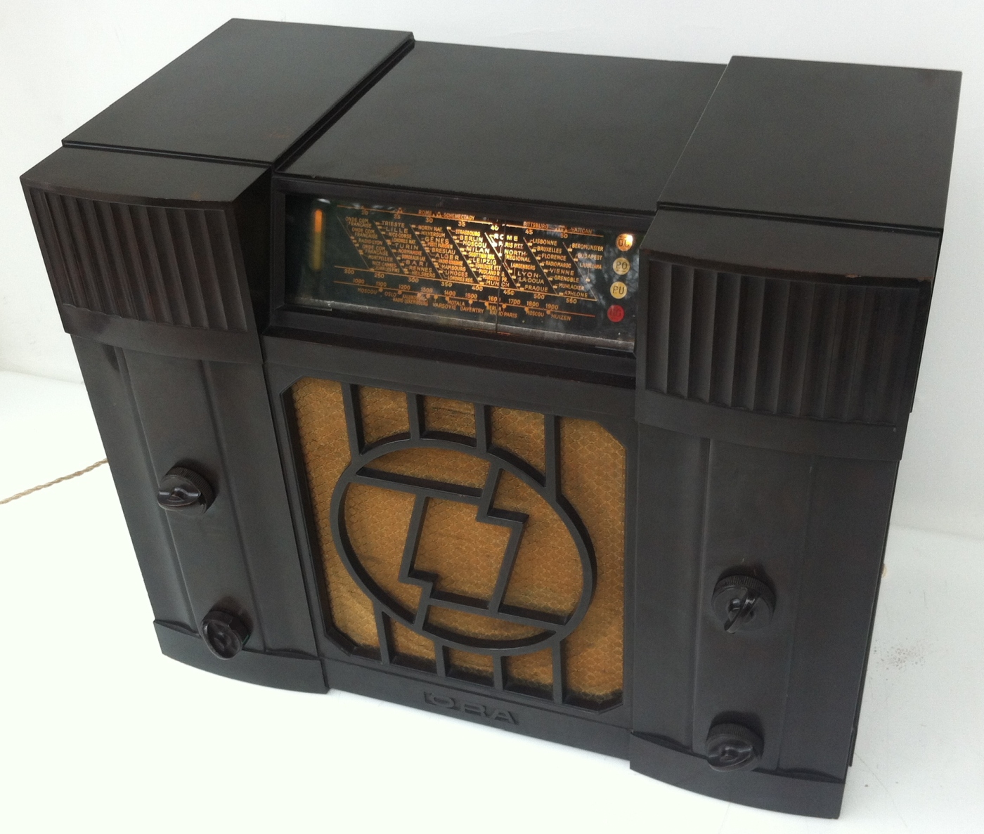
Many years ago - in the mid-eighties - I managed to acquire this O.R.A. radio, a superhet receiver, originally equipped with the tubes AK2, AF3, ABC1, AL3, AZ1.
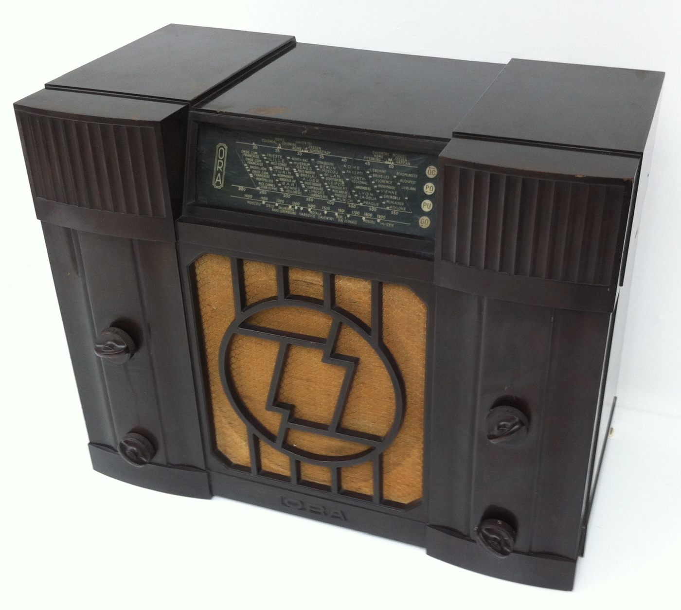

Experienced collectors of French radios know that the model identification of radios built by the French enterprise O.R.A. (ORA, ORADYNE) can be a difficult task. This applies in particular to the models released by ORA around the mid-thirties. During this period ORA adopted the strange habit of neither identifying their radios by inscriptions on the rear panel nor by type labels on the chassis, causing a fair amount of confusion in the radio collectors’ community.
Since at the time of my aquisition there was little information on vintage radios available in the internet, I decided to clean it, put it into the shelf and wait.
There it hibernated for the past 33 years until recently a friend asked me to look after his own ORA radio which turned out to be very similar to my model. As a matter of fact it contained some components that were missing in my own set. This unexpected coincidence re-ignited my interest in this radio and I decided to have a closer look.
Unfortunately the internet is still not very abundant when it comes to reliable information for this type of radio, but I finally managed to identify a number of radio models for which ORA had used the same cabinet.
These are
'S536', 'S537', 'SU636', 'L636' and 'LU636'
Since model 'S537' was equipped with PHILIPS red series tubes, and 'SU636' and 'LU636' were for AC/DC mains operation equipped with a mixture of A- and C-tubes, only models 'S536' and 'L636' remained as possible candidates.
As we will see, my ORA radio is a model 'S536', whereas that of my friend is a model 'L636'.
2 ORA model 'S536'
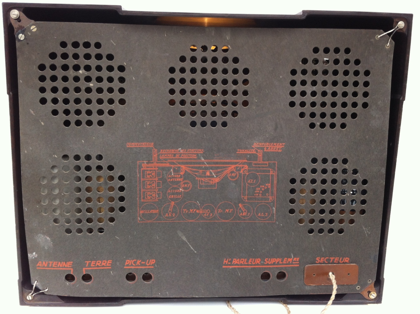
The rear panel of my ORA radio shows no sign of a model name - just a sketch of the chassis top components and the tube line-up: AK2, AF3, ABC1, AL3, AZ1. The AL3 had been replaced by an AL4, having almost the same electrical data as the AL3.

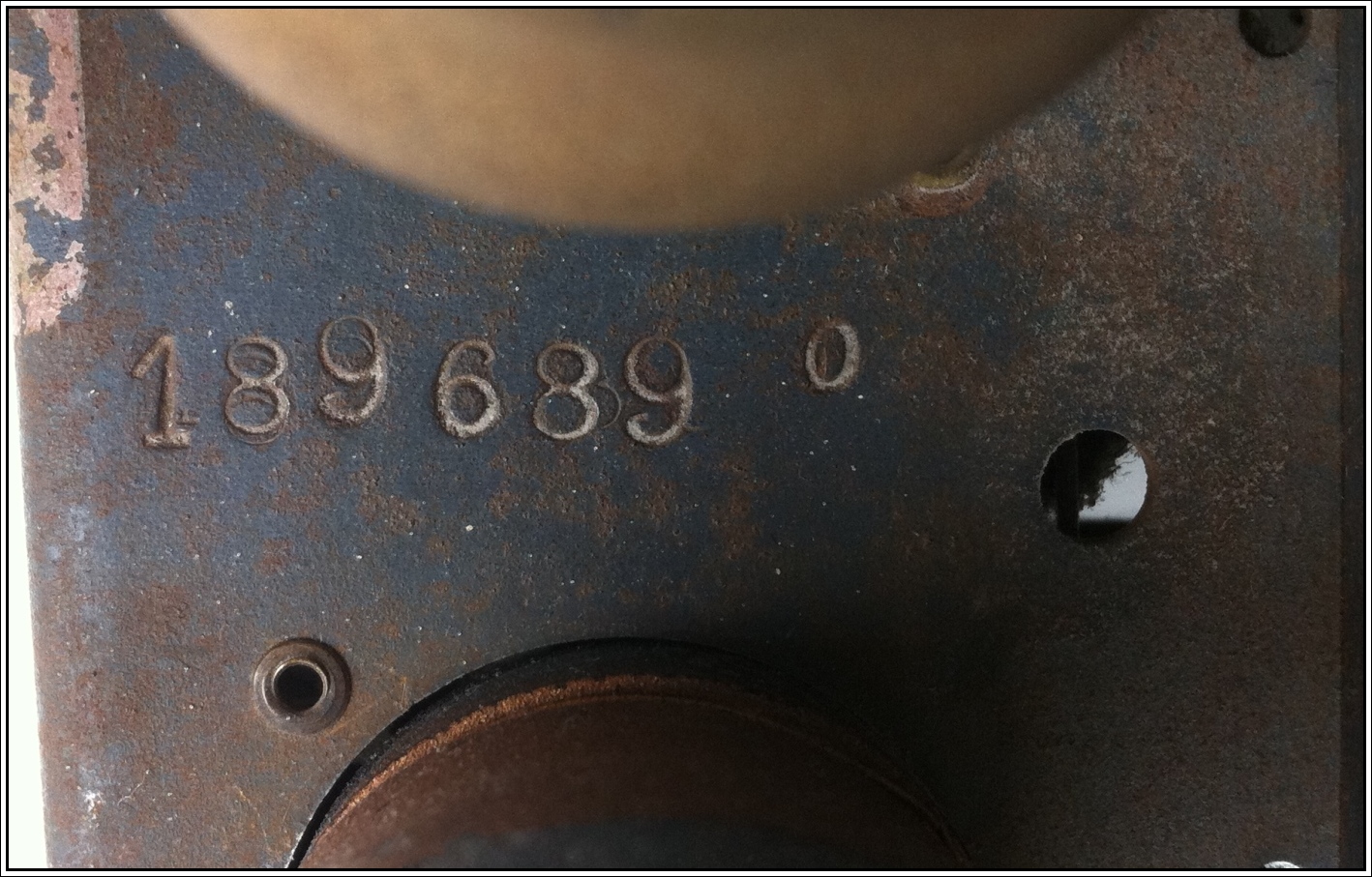
Removing the rear panel one finds that the sketch corresponds to the chassis layout, but here again, one finds no sign of a model identification - just the embossed serial No:
But having a closer look at the the print on the rear panel and on the chassis one finds some surprises:

- In the upper left part of the print it says: 'LAMPES DE POSITION', which means that there should be pilot lamps attached to the tuning dial frame, indicating the position of the waveband switch.
- On the upper right hand side there had been an inscription that had been erased
- Another erased print is found between the 8MF capacitor and the IF- filter (Tr. MF.)
A closer look reveales the former prints:

The print on the right hand side read: 'REGLAGE VISUEL' meaning that there should be a tuning indicator attached to the tuning dial frame. We will later see, that a 'shadow indicator' was used in these radios.
The missing print underneath the 8MF capacitor indicated the position of a tube AC2.
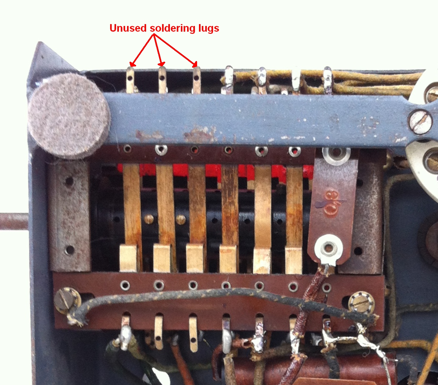
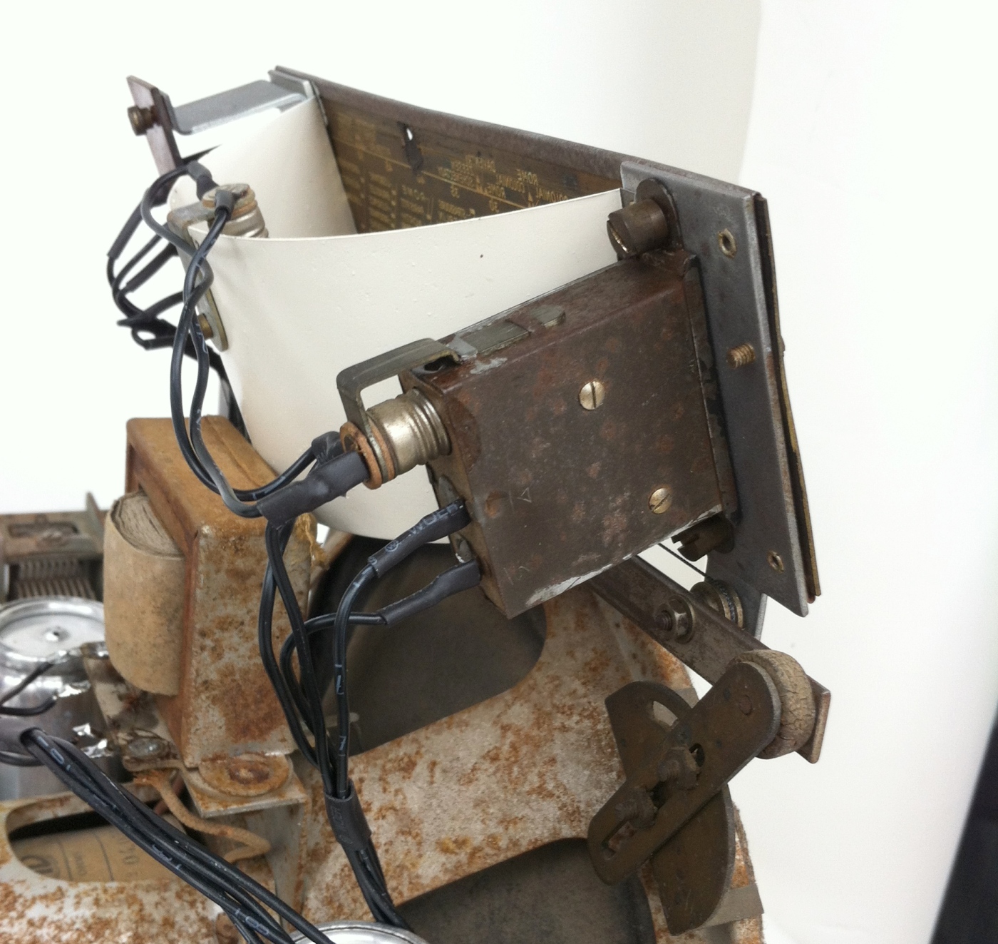
However, as one can see in the picture below, the tuning dial frame shows no traces of a fixation that could have held the waveband indicator lamps or the tuning indicator. A picture of the waveband switch contacts shows that there are solderung lugs that were doubtlessly foreseen for the pilot lamps, but never used.


The window on the left hand side of the celluloid dial plate, behind which the tuning indicator should have been positioned, shows the ORA company logo, whereas the windows on the right hand side behind which the waveband indicator lamps should sit, show faded coulours. In my set the chosen waveband was indicated by cossesponding colour marks on the knob of the waveband switch.

Furthermore in the place where the AC2 should sit on the chassis, there is only a hole that has been closed using a piece of aluminium. The aluminium has been riveted onto the chassis using the same type of rivets that were used for mounting the tube sockets. So one can conclude that we are not confronted with an à posteriori modification, but that this was already done at the time of fabrication.
What does that tell us? Apparently, the same cabinet, chassis and rear panel were used for two versions of the - in principal - same model:
Version 1:
My 'Low Budget' model described above: The Standard 5 tubes 1936 model 'S536', in which all luxury components, that were not essential for the function of the radio were omitted. Rather than manufacturing an individual chassis and rear panel, the surplus hole in the chassis was concealed using a piece of metal and other missing components were simply erased from the sketch on the rear panel.
and for
Version 2
The 'de Luxe' 6 tubes 1936 model 'L636' with (i) waveband indicator lamps, (ii) a tuning indicator and (iii) an extra triode AC2 which, as will be seen later, was introduced as a driver for the shadow tuning indicator.
NB: As can be seen in this 1936 advert, ORA was frequently using the letter 'S' for the standard version of a radio model and 'L' for the 'de Luxe' version with all kinds of extras.

But what did the 'de Luxe' version 'L636' look like?
3 ORA model 'L636'

Chosen waveband MW (PO=petites ondes) , shadow tuning indicator about half deflected. Readers interested in learning more about the functioning principal of shadow indicators are advised to read this comprehensive article in RMorg.

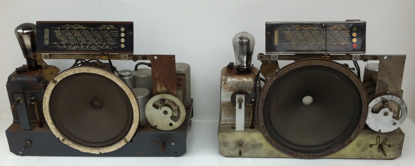
'S536' chassis top view 'L636' chassis top view


A close-up of the 'L636' tuning dial frame:
The waveband indicator lamps The shadow tuning indicator

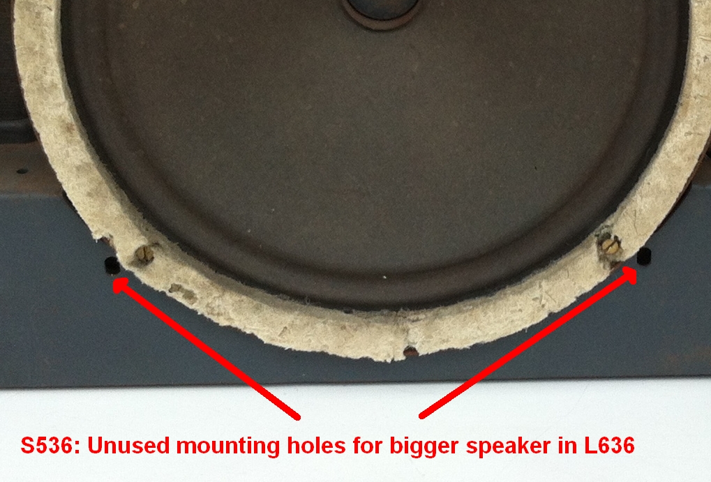
Apart from the tuning indicator and the waveband lamps and the extra tube AC2, there is another significant difference between the 'L636' and the low budget model 'S536', that was not mentioned before: the size of the loudspeaker:
'S536' speaker dia: 21 cm 'L636' speaker dia: 24 cm
4 Comparison of the wiring of the ORA models 'S536' and 'L636'
The first picture shows an overwiew of the under chassis wiring of the 2 models.
'S536' 'L636'
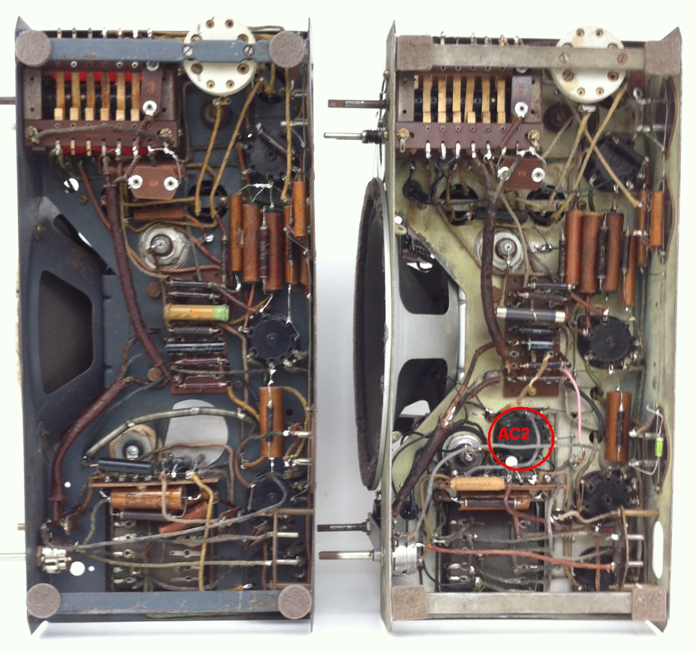
Apart from some very minor differences and the AC2 socket, the wiring of the 2 chassis is identical. This becomes even more obvious in detail pictures:
'S536' 'L636'


The following 2 pictures show the only difference in the chassis wiring:
'S536' 'L636'


In the case of model 'L636' the little wiring board next to the AC2 position carries 2 more resistors, the AC2 cathode resistor of 2 kΩ and the AC2 anode resistor of 60 kΩ in series with the shadow tuning indicator. Details will be shown below in the schematic diagram of the two models.
5 Schematic diagram
The schematic diagram was not completely redrawn from scratch, but that of model ORADYNE 'R57' originating from the 'Schémathèque toute la radio' was used as a basis and modified where necessary.
Apart from the final amplifier tube (AL1 in 'R57' vs. AL4 in 'S536' and 'L636') and some minor component value and wiring changes, the schematics are very similar.
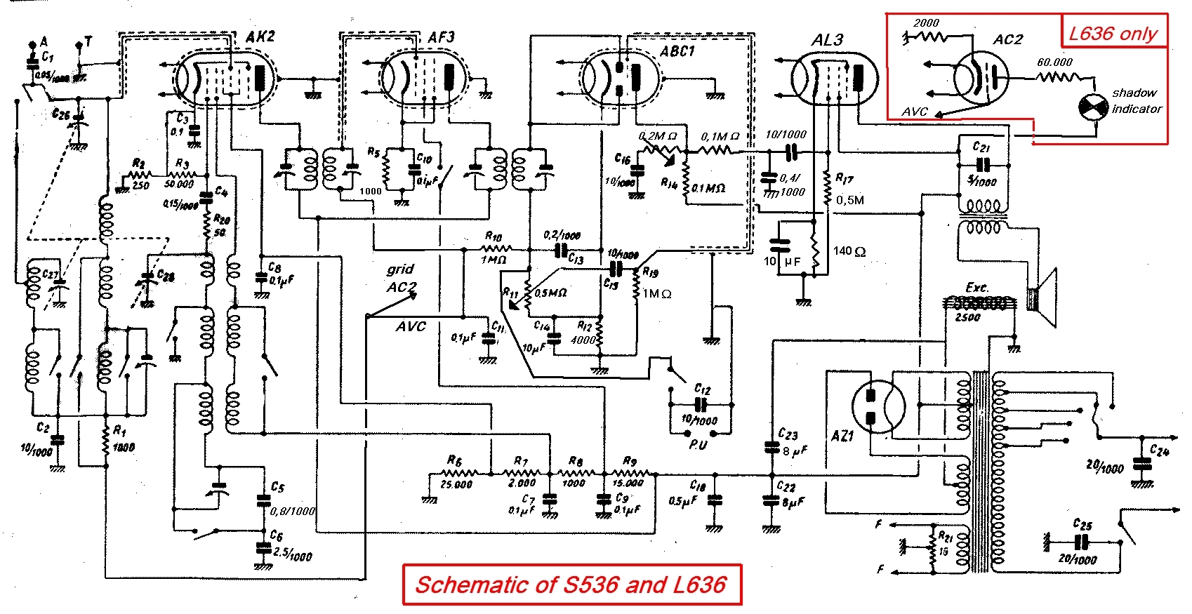
This schematic diagram corresponds to the real wiring of both, the 'S536' and the 'L636' that I had at my disposition. It shows the typical layout of a mid-thirties superhet radio with band pass filter input, an octode mixer, a variable-µ pentode in the IF-amplifier stage, a diode-triode demodulator / AF preamp and the latest generation power pentode.
The only detail in which the two models differ is the shadow tuning indicator and its driver tube AC2 (the components inside the red frame in the above picture).
There are neither components that would allow calibrating the deflection of the shadow indicator vs. AVC voltage, nor for setting the zero-position with no input signal. This means that replacing an old AC2 by a new one would change the length and deflection-sensitivity of the shadow bar. Apparently, at the time when this model appeared on the market this was considered a point of minor importance for the radio listener community.
My sincere thanks to Dietmar Rudolph and Hans Knoll for proofreading and helpful advice!
To thank the Author because you find the post helpful or well done.