- Pays
- Allemagne
- Année
- 1952/1953
- Catégorie
- Radio - ou tuner d'après la guerre 1939-45
- Radiomuseum.org ID
- 14707


- No. de tubes
- 7
- Principe général
- Super hétérodyne (en général); FI/IF 473/10700 kHz
- Circuits accordés
- 7 Circuits MA (AM) 9 Circuits MF (FM)
- Gammes d'ondes
- PO, GO, OC et FM
- Tension / type courant
- Alimentation Courant Alternatif (CA) / 110-240 Volt
- Haut-parleur
- HP dynamique à aimant permanent + bobine mobile / Ø 24 cm = 9.4 inch
- Matière
- Boitier en bois
- De Radiomuseum.org
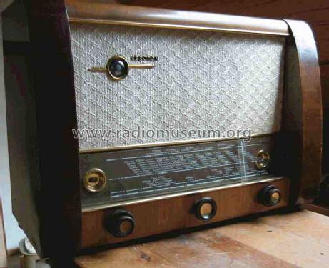
- Modèle: Heroton H894W - FWF, Funktechnische Werke
- Forme
- Modèle de table profil bas (grand modèle).
- Dimensions (LHP)
- 615 x 430 x 310 mm / 24.2 x 16.9 x 12.2 inch
- Remarques
- variable Bandbreite.
- Poids net
- 15 kg / 33 lb 0.6 oz (33.04 lb)
- Prix de mise sur le marché
- 398.00 DM
- Source extérieure
- E. Erb 3-907007-36-0
- Source
- Kat.d.Rundf.GrossH.1952/53 / Radiokatalog Band 2, Ernst Erb
- D'autres Modèles
-
Vous pourrez trouver sous ce lien 39 modèles d'appareils, 27 avec des images et 12 avec des schémas.
Tous les appareils de FWF, Funktechnische Werke Füssen, Möst & Henning KG; Füssen+Öhningen (Heroton)
Collections
Le modèle Heroton fait partie des collections des membres suivants.
Contributions du forum pour ce modèle: FWF, Funktechnische: Heroton H894W
Discussions: 1 | Publications: 1
Last december, I bought an Heroton 894W (1952) which is in very good condition.
The Schema of the 894W is not yet available on the Radiomuseum site (and it said that it is required!)
I downloaded the available schema of the model H983W (1951).
Undeed, the schema are very close, even if some tubes are different.
From the 1951's H983W to the 1952's H894W
-on the FM front end , the EF85 has been replaced by an EF80 (the straight pentode),
-the first IF tube EF11 (Y8A socket) is replaced by an EF85 (Noval)
-the second IF tube EF15 (Y8A socket) is replaced by an EAF42 (Rimlock)
-the double diode and first audio tubes EAA91 and EBF11 are replaced by the single complex EABC80.
-the symmetric (to the ground) ratio detector of the H983W is replaced by an asymmetric one. The zero crossing adjustment will need a slightly more complicated procedure (the need of an external resistor bridge)
One might remark that the EF11 has characteristics similar to the ones of the EAF42 (slope 2,2 ma/V),
and the EF15 is not far from the EF85 (slope 5,5mA/V, similar output impedance).
So, from one radio to the other, high slope and lower slope tubes have been permuted.
I noticed that, on the EF85, neutrodynage is performed with the screen grid, and this was not done on the EF15.
Both radios have a push and pull switch on the tuning knob to select, in AM, between narrow and broadband IF. On the H983W, one can find the coil switching device on the primary coil the last IF transformer filter (in the EF15 anaode circuit), whereas on the H894W, that we are interested in, the switched coil is on the secondary coil of the previous IF transformer, in the grid circuit of the EAF42. So, the last AM-IF stage may be less exposed to crossmodulation on the H894W.
Other differences may be found in the Audio section. On the H983W Audio amplifier, there was only a negative feedback loop on the final audio stage EL11, namely between the EL11 Anode and the EL11 Control grid. The input triode, and the output transformer are not controlled by any feedback. Now, on the H894W the global negative feedback is adopted, from the secondary of output transformer (right on the loudspeaker) back to the "foot" of the volume potentiometer, as is found on many radios.
About tone control, and global tone shaping, on the H894W, there is a fixed and generous enhancement of the bass within the feedback loop. The treble may be adjusted with a single potentiometer acting as a mixed control. Towards one end of the potentiometer course, there is a progressive treble enhancement using the feed back loop, and towards the other end of the potentiometre course, there is the treble reduction by a capacitive load on the triode anode load. The resistive law of the potentiometer for such a dual control would have been difficult to optimize, so the variation is not as progressive on both ends.
It is always puzzling to me to find a tone control within the circuit of an amplifier which is globally controlled by a feedback loop. Though, as one can calculate, it is true that the feedback loop control is not so tight, but nevertheless.... Phases are part of the "secrets".
All the rest of the schema have strong similarities, and the schema of the H983W will really help you to understand and track problems on the H894W.
In particular, on both radios, the grids polarization voltage is obtained from a serie resistor on the negative output of the rectifier bridge (as was often found on older radios).
On both radios, the ECH42 is used as muliplicative mixer for both AM and FM. So switching is performed right on the oscillator circuit! You'd better get clean contacts in this area....
More recents radios adopted separate specific mixers for FM and AM, and that avoids switching on the local oscillator circuit which is getting delicate at 100MHz, when one likes to build a stable oscillator.
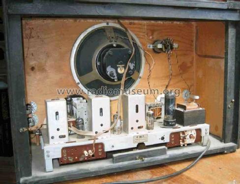
Then if you look at the photos of the chassis, as seen from the back, you will admit that the two radios look pretty the same. So the procedures of building the two radios, of disposing and connecting the components together are probably very similar.
As is often the case, many capacitors got dry, getting less capacitive, and losing their by-pass or filtering effects. As I was doing the FM-IF alignment, the radio started to hiss and turned into a beautiful 10MHz generator. There was still some capacitors to be changed, which ones? ....later on, it got better.
This radio with its 24cm loudspeaker sure sounds very nice.
Yves Barbin, 11.Feb.21