Majestic 4006U Export
Grundig (Radio-Vertrieb, RVF, Radiowerke); Fürth/Bayern
- Hersteller / Marke
- Grundig (Radio-Vertrieb, RVF, Radiowerke); Fürth/Bayern
- Jahr
- 1959/1960
- Kategorie
- Rundfunkempfänger (Radio - oder Tuner nach WW2)
- Radiomuseum.org ID
- 135372
-
- anderer Name: Grundig Portugal || Grundig USA / Lextronix
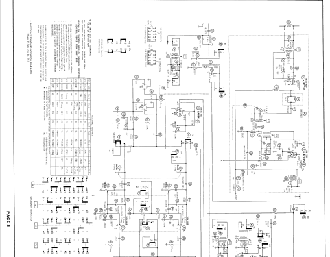
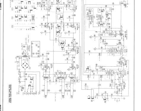
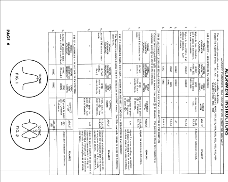
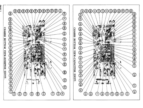


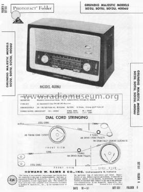
Sams PhotoFact Set 551 Folder 6 Date 10-61
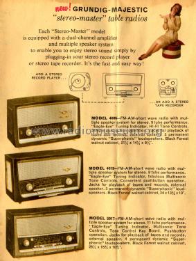
Picture from Grundig Majestic Brochure

Picture from Grundig Majestic Brochure
Klicken Sie auf den Schaltplanausschnitt, um diesen kostenlos als Dokument anzufordern.
- Anzahl Röhren
- 8
- Hauptprinzip
- Superhet allgemein; ZF/IF 460/10700 kHz; 3 NF-Stufe(n); Exportmodell
- Anzahl Kreise
- 6 Kreis(e) AM 10 Kreis(e) FM
- Wellenbereiche
- Mittelwelle, Kurzwelle und UKW (FM).
- Betriebsart / Volt
- Wechselstromspeisung / 110-120; 220 Volt
- Lautsprecher
- 3 Lautsprecher
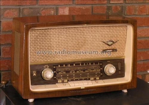
- Material
- Gerät mit Holzgehäuse
- von Radiomuseum.org
- Modell: Majestic 4006U [Export] - Grundig Radio-Vertrieb, RVF,
- Form
- Tischgerät, Tasten oder Druckknöpfe.
- Abmessungen (BHT)
- 540 x 360 x 240 mm / 21.3 x 14.2 x 9.4 inch
- Bemerkung
-
The Grundig Majestic model 4006U is the export version of the domestic Grundig "Konzertgerät 4006 Stereo". SAMS Photofact date 10-61, set 551, folder 6 shows for the same chassis the Grundig Majestic models 4006U (as table version) and the consoles with legs: SO2U, SO11U and SO12U. The SW band covers 5.9 to 16 mc. Two loudspeakers have a diameter of 5" the third 7" x 11".
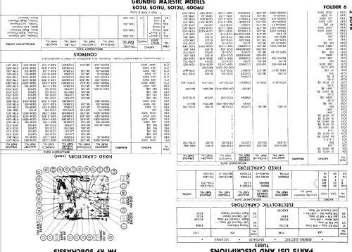
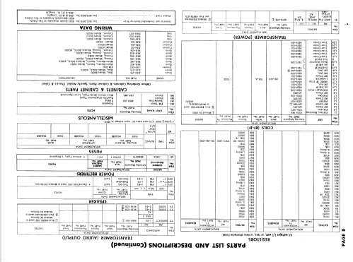
- Literatur/Schema (1)
- Photofact Folder, Howard W. SAMS (Date 10-61, set 551, folder 6)
- Autor
- Modellseite von Ernst Erb angelegt. Siehe bei "Änderungsvorschlag" für weitere Mitarbeit.
- Weitere Modelle
-
Hier finden Sie 6250 Modelle, davon 5496 mit Bildern und 4252 mit Schaltbildern.
Alle gelisteten Radios usw. von Grundig (Radio-Vertrieb, RVF, Radiowerke); Fürth/Bayern
Sammlungen
Das Modell Majestic befindet sich in den Sammlungen folgender Mitglieder.
Forumsbeiträge zum Modell: Grundig Radio-: Majestic 4006U
Threads: 1 | Posts: 2
I have aquired a 4006u. It is a beautiful radio but has some problems, The back and the power cord are missing. Of greater concern the power screw seems to be missing, This is all guess work on my part. There are two tapped holes under the fuse that are marked 110 and 220. In pictures of similar units I can see that there is a plastic capped screw in the 110 hole. I see the connection on the schematic and can see that it does connect either the 110 or the 220. My question is does anyone know about how long the screw is? I don't want to go too long and screw into some vital part and ruin it or too short and not make connection. I am assuming that I can use a regular screw here and that the specific screw is not available. If anyone knows of a source for the plastic capped screw that belongs here i'd be glad to hear of it. I have discovered that the fuse has been covered with aluminum foil so I am currently assuming there are power problems to be fixed once I can connect the power.
Thanks in advance for any help or suggestions you may have.
John
John Kennedy, 04.Dec.10