- Pays
- Royaume Uni
- Fabricant / Marque
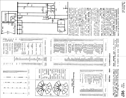
- HMV (Brand), His Masters Voice, The Gramophone Company Ltd.; Middlesex
- Année
- 1950
- Catégorie
- Radio - ou tuner d'après la guerre 1939-45
- Radiomuseum.org ID
- 105058

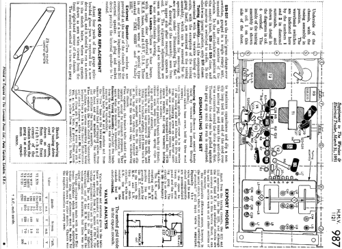
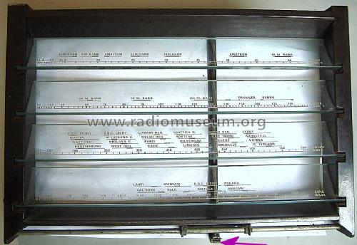

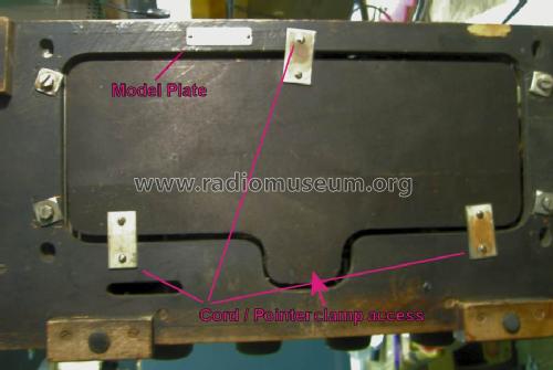
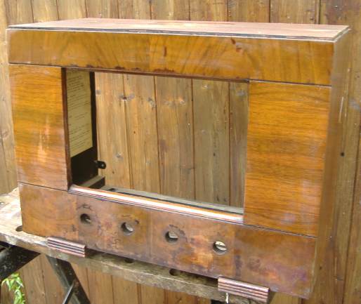
Details of drive cord lacing

Cliquez sur la vignette du schéma pour le demander en tant que document gratuit.
- No. de tubes
- 5
- Principe général
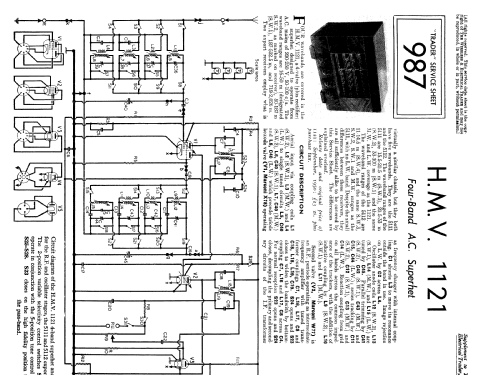
- Super hétérodyne (en général); FI/IF 465 kHz
- Circuits accordés
- 6 Circuits MA (AM)
- Gammes d'ondes
- PO, GO et 2 x OC
- Tension / type courant
- Alimentation Courant Alternatif (CA) / 200 - 250 Volt
- Haut-parleur
- HP dynamique oval à aimant permanent / Ø 8 inch = 20.3 cm
- Matière
- Boitier en bois
- De Radiomuseum.org
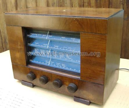
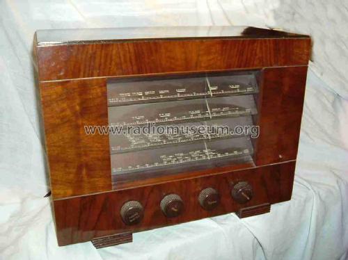
- Modèle: HMV1121 - HMV Brand, His Masters Voice,
- Forme
- Modèle de table profil bas (grand modèle).
- Dimensions (LHP)
- 457 x 348 x 255 mm / 18 x 13.7 x 10 inch
- Remarques
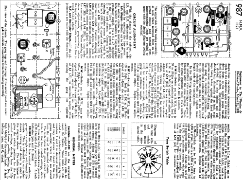
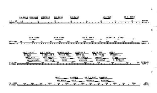
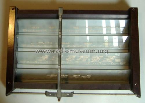
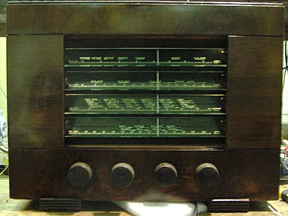
- The model HMV 1121 was released in September 1950 and has an unusual tuning scale with four louvered strips of glass (one for each of the wavebands covered) with the loudspeaker mounted behind. The wave bands are 16 to 50 m and 50 - 187 m for SW, 187 to 582.5 m for broadcast and 719 to 2026 m for long waves.
Two export receivers employ a very similar chassis, but they both have five wavebands. The wave bands of the 5112 are 11 to 14.5m (SW4), 15.5 to 20.5m (SW3), 20.5 to 33m (SW2), 33 to 100m (SW1), 187 to 582.5m for Medium Wave (Broadcast) and 719 to 2026m for Long Wave. The 5111 has LW with like the 1121 instead of 11 to 14.5m (SW4)
- Poids net
- 11.5 kg / 25 lb 5.3 oz (25.33 lb)
- Prix de mise sur le marché
- 24.00 GBP
- Schémathèque (1)
- Radio And Television Servicing books (R&TVS)
- Auteur
- Modèle crée par John Koster. Voir les propositions de modification pour les contributeurs supplémentaires.
- D'autres Modèles
-
Vous pourrez trouver sous ce lien 429 modèles d'appareils, 338 avec des images et 244 avec des schémas.
Tous les appareils de HMV (Brand), His Masters Voice, The Gramophone Company Ltd.; Middlesex
Collections
Le modèle fait partie des collections des membres suivants.
Contributions du forum pour ce modèle: HMV Brand, His: HMV1121
Discussions: 6 | Publications: 6
This is one of the Mains sets I fancied even before collecting
It was packed accoring to my instructions including two layers of card with balls of paper between in front of the glass.


Appearance identical to the eBay photo
In the early 1970s as hobby I repaired old TVs and Radios. Later in 1978 I repaired current "AV" equipment as part of my job, getting it "fixed" was more important than originality!
But with Vinatge (this radio is about 62 years old at time of writing) or collecting there is the conflict between "use" (a Radio is meant to be listened to) and "Museum"/"Archaeological" approach to restoration or preservation. I'm not going to buy an old AM set and build in an FM head, or strip an old set and put in LCD screen and DAB radio. But for 1950s set I'm not going to use original resistors or capacitors. I regard a plug-in tube adaptor acceptable but changing base type or rewiring the socket for different type of valve unacceptable. What would I do with a 1920s set? Maybe leave it as a display piece if I can't repair using original parts? I have a 1934 Philips Superinductance and can't decide what to do about it!
See the cabinet "minimal" restoration on this article (link).
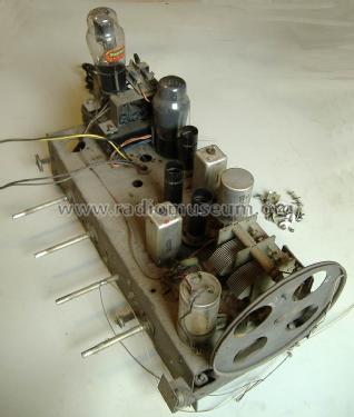
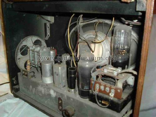
I first printed large copy of the schematic with the two pages combined to one and also the component layout on one page and took a photo of under the chassis (see Model Photos):
 Click for larger preview

Reduced size example of component layout
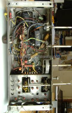
I indentified possible significantly faulty capacitors and looked for C24 the Anode DH77 to KT61 Grid (via S28 or C25 and R16) from the photo, schematic, usage, type and value. See "Replacing old Capacitors"
C24 is a metal can type and one end not easily accessible. C32 is a very large wax coated card cased Waxed Paper capacitor, so I disconnected the V4 anode end and put the capacitor leakage tester on it. It flashed slowly which indicated over 100M Ohm leakage at 300V. Not at problem at all!
So I powered up the set after I repaired the broken volume control. With the speaker off the baffle board it sounded terrrible but worked. Switching to any of the tone positions 1 to 4 there was a smell of burning and R20 started to glow! Ooops. Time to turn off!
I took out the KT61 output Beam Tetrode and plugged the DMM between grid and ground.(pin 5 is grid and 2 or 7 heaters). On powering up the DMM read 5 V. Bad. Should be near zero.

So obviously the "metal can" (often high quality ex-military paper capacitors in 1950) capacitor is useless.

It's got a rubber or plastic cover.
I replaced it with a 1uF 630V metalised polyester, which should be fine here.
Everything now happy? Well, unusually all the card & wax covered "wax" paper & foil capacitors seem fine. The set does use very many wax coated Silver Mica capacitors which rarely give trouble.
No, the SW2 band is totally dead. Even with local signal generator. Here is why (link) with repair.
Now everything is fine.
One bulb is gone, so I replaced all four with new 6.5V 300mA.
The loudspeaker cloth splits on re-assembley, so as I don't have similar dark coppery open mesh cloth to let the black baffle and speaker be a scale background I use a piece of coloured very sheer skirt.
Here is the set running on the bench with main lights off to make the scale illumination more visible
It works quite well on LW, MW, SW1 and SW2 with just about 1.5m of aerial wire (5'). There is no internal aerial, without some sort of aerial wire it receives nothing, which is normal.
The chassis actually has octal socket holes for the X78, W77 and DH77. There is an octal size hole too close to speaker at the front that the U10 wires come from. I suspect the chassis tooling is from the HMV 1120 which looks like same steel with Octal lineup of tubes.
I used the signal generator to check aligment (I only adjusted replacement C41 on SW2) and then to set tuning to a known position near the scale middle. I put a mark on the scale (there is a pointer) of the large drive cord wheel. This allowed near perfect "first attempt" clamping of dial cord to scale pointer on chassis refitting.
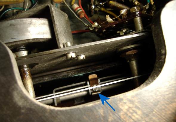
Drive cord to scale pointer clamp via underneath access hatch
Other Features
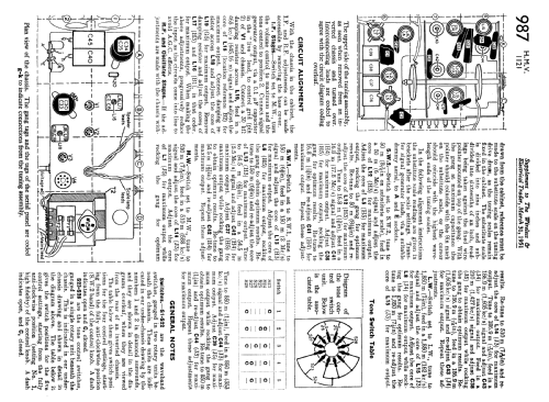
The Tone control is interesting. It has five positions:
- HiFi: Maximum treble and IFT 1 (L16 & L17) tuning swtiched to wider band, no treble reducing feedback
- High: Slight treble cut (C27 27pF feedback)
- Medium: Medium tone (C28 68pF feedback)
- Low: Maximum Treble cut (C29 200pF feedback)
- Bass Cut: dramatic bass cut by insterting 470pF C25 in series with KT61 grid with 330K grid bias load, also Maximum Treble cut.
The Radio/Gram switch is on the rear rather than on tone switch (Pye 39 JH, Pye 38 JH/E) or on waveband switch.

Final Result
(larger size uploaded to model)
Michael Watterson, 05.Jul.12
The HMV 1121 was missing the SW2 band. This is the highest band, so it could be the X78 valve (tube) is low as more gain is needed at higher frequencies. Or the waveband switch could be faulty. Perhaps some other fault.
I don't have a spare X78, in fact it might be the only Triode Hexode in B7G package and not used in many sets. I do have a few 6BE6 / EK90 heptode tubes. I read that some people have an HMV 1121 with a 6BE6, A poor solution as base needs rewired and likely much poorer. An adapator with ECH81 or EK90 + EC90 would be far better performance.
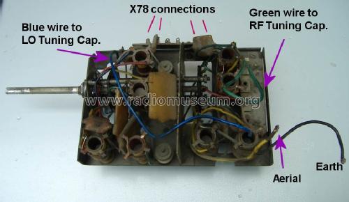
It seems though that because there were three variations the coil/capacitors for local Oscillator (LO) and RF is on a subchassis, Easily removed (but note which wires/parts go to what terminal, especially the X78 connections!). But first i cleaned the switch and checked the continuity on Ohms of the DMM. Switch S12, S19, S8 and S1 fine.

Second I thought the LO coil was faulty. Examination with both scope and spectrum analyser confirmed absolutely nothing on SW1 Triode Anode (oscillator) and even IF break through very low.
The voltages on empty socket identical on SW1 and SW2.
But actually only two of the 4 top tags connect to coil. One has nothing and one is just a mount for C9 grid coupling capacitor of Triode section of X78. I resoldered the wires in case of a fracture and thus open cicuit L12 when mounted (L12 is fine wire under L9, heavier wire). Still nothing on reassembly.
C11 and C41 are the only two other possibilities. C11 is Silver Mica and indeed passed 350V leakage (none) and measured close to correct value. Surely not the "beehive" trimmer (C41). Well it was short circuit.
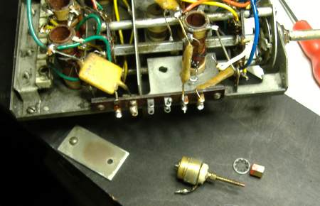
C41 removed from chassis

C41 dissassembled
All attempts to "repair" it failed. Even the slightest engagement of the two halves would result in a short. Cleaning, filing, sanding etc tried.
I do have a few Philips "beehive" trimmer capacitors, these have more concentric cylinders but spacing is greater so maybe not so much different in value (C41 value not listed). Physically they are not the same. Maybe I can poke the earthy spike through chassis hole and the fixed part solder to chassis? The disadvantage is that the normally "earthy" turning part becomes "RF live". But it does mean no modification to the chassis. If solder cleaned, the original type can be fitted in the future.
I used SMD hot air re-workstation to heat the chassis to solder after scraping of a little plating.

The normally "live" fixed part soldered direct to chassis.
A small wire link used to connect the normally "earthed" part to "RF live" coil under the chassis

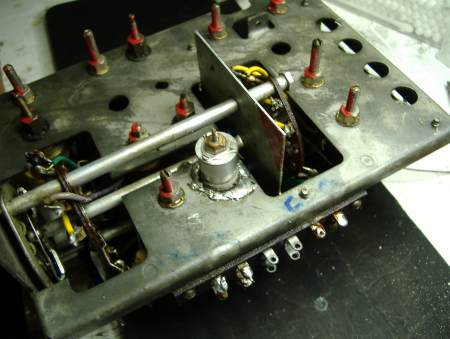
Underside of RF/LO chassis with top of new C41 screwed on.
I put the adjustment at about 1/2 way to start with:

Sub-chassis remounted in main radio chassis
Amazingly I found that the frequency was only about 6mm out on the SW2 scale. Of course the tuning capacitor is "RF live" but not DC live. You need to "withdraw" to check frequency. A few drops of candle wax used on the screw thread/cap top to "lock" the capacitor after adjustment at about 16MHz.
Michael Watterson, 05.Jul.12
The volume control spindle fell out. In this case not due to pulling the knob off as the knobs come off easily on the HMV 1121. These old long shaft high value logarithmic potentiometers (log pots) with a mains switch are hard to get so can it be repaired?

Well, the first stages are to take it out of the radio (making a note of where the wires go) and then carefully prise up the tabs holding on the cover & switch.
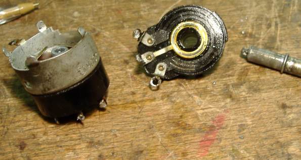

It seems like the steel shaft is forced into an interference fit alloy splined socket rather than the more common rivited construction. The start of the track looks badly worn, the solutions are silver PCB repair paint or to bend the two wipers away from previously used part of track or else the volume won't fully turn down.
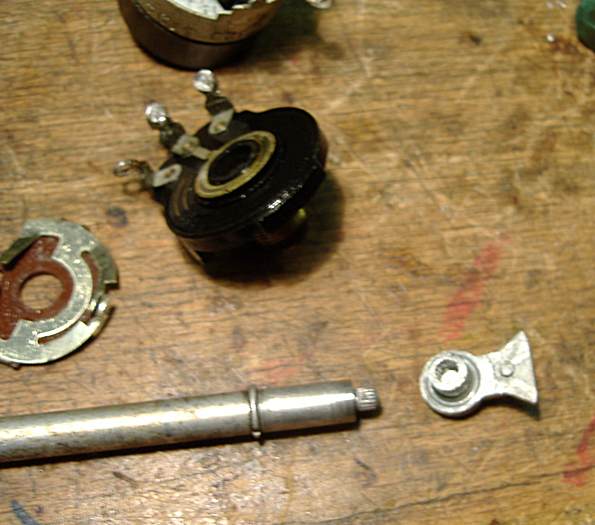
Check no parts are broken and clean / degrease (alloy debris removed from stee shaft). The paxolin base with wipers (to left near shaft) is first "super glued" to the Alloy back plate (to right of shaft).
The shaft is held in vise and super glue put on splines, Then a single strong blow using a pin or bolt:
After a single hard thump!
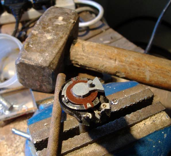
Then test the "pot" with a meter.
Make sure the on/off switch works on both poles (may need switch cleaner and operated a few times) and put it in the "on" position.

Switch in "on" position
Then if everything is working insert into panel but solder wires before adding the nut.

Michael Watterson, 05.Jul.12
Though I mostly collect Battery Tube sets this 1950 set always fascinated me. Coincidently it arrived by courier (9.05am) the same day Wolfram Zylka (also a member here) visited me. He pointed out that it wasn't as unique as most British people think. Telefunken did it first!
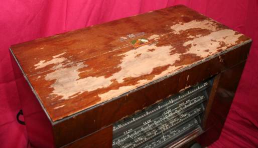
The set of course cost me x3 as much for shipping as actually buying it! On the eBay photograph it didn't look worm-holed or broken, just very shabby with large areas of varnish flaking off the top.
ebay photos matched reality
I advised the seller to completely fill the inside with balls of newspaper after moving tuning to the maximum wave end, vanes inside closed, and then pack twists of paper between the glass slats.
Then to put cardboard on front, excluding knobs, then more balls of paper and another card. Unfortunately I forgot to warn him not to tape direct to case, so some tape removed more loose varnish :-(.
I told him to fill round in the box with scrumpled balls of newspaper too. He followed my instructions exactly and the radio set arrived matching the photos exactly. Which was really very good as he was selling it "Collect in Person only" and I persuaded him to use Courier. Using a reseller it's mysteriously about 1/4 the price of the direct retail purchase, or a about 10% cheaper than a "cheap courier"!
Obvious Positives and faults
The tuning cord was snapped, the dial pointer assembly seemed to be jammed.
The glass and dial print in perfect condition (so I carefully cleaned and scanned them).
Bare wood exposed by flaked varnish, small bits of logo missing.But veneer fairly good and no woodworm.
Everything inside intact (except snapped cord) and appeared orignal. Back cover in astounding condition, except leather strap hinges snapped.
I took out chassis (see model pictures) and indeed underneath all seemed original.
The Cabinet.
This is often more work and much trickier for me than the Electronics. So I do it first! I decided not to strip and redo toner or stain. I certainly would not normally consider French Polish or "Danish oil", I doubt any 1940s or later set ever finished with either. I decided on a minimalist approach of clean, gentle rub with "white Spirit" and then "methylated spirits". The speaker baffle was very greasy with soot. I think as if the set was in a house with a chimney fire once,

I gave scratched and bare areas alternately a touch up with a "furniture scratch" repair pen of suitable tint and rub with methylated spirits.

Freeing the scale pointer was just a matter of WD40, wipe off and then a light oil. Probably Graphite would be better.
Next I unpeeled the speaker cloth (a coppery effect very open mesh) and cleaned it.

Sadly it split when being reattached to the baffle board. So I coloured a piece of sheer (almost see through) skirt fabric.
I resprayed the baffle board matt black and cleaned the speaker cone.
I used several coats of Acyrilic varnish. Extra on the bare wood of the top.
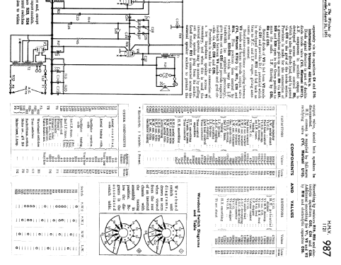
The dial cord was replaced with Builders "Tile" cord, waxed with a candle. You can buy real woven fishing line (that might be linen), but it's 250m reels at €25 and the Tiling cord seems to work (€2 for 100m). I've also used €2 child's "crab line" on some sets. I think it's possible to figure out the arrangement, but the service sheet shows it clearly. See the composite model photograph.
One Dial Bulb was gone so I replaced all four with new 6.5V 300mA type purchased from a Gentleman in Scotland.

Jumping Ahead: Reassembled with cleaned glass, varnish dry and new speaker cloth.
I might replace the broken leather straps but for now I used impact adhesive to join the breaks.
Next
The spindle fell out of the volume /on-off control. I'll do a separate article about how I fixed it.
Then the Electronics!
Michael Watterson, 05.Jul.12
Each scale glass is 290.5mm long and 38mm wide. About 4mm thick.
On the 300dpi scan uploaded the "graduated" part of the MW scale is 225.5mm long. There is a 600dpi scan, but too large to upload!
Clear Laser Decal paper will give black water-slide transfers of the text. To achieve "white" either use a "White" cartridge in an Alps printer, or with suitable laser/copier toner a White (or metallic) thermal transfer sheet can be passed on the Decal print out through a laminator and peeled off to leave white on the black (remelted) toner.
Not all toners work.
Michael Watterson, 02.Jul.12
The tube line up is an unusual mixture (for 1950 UK) of B7G, Octal and 1930 4 pin. Perhaps an RCA influence as "mains" B7G tubes mixed with other tubes is quite common on US sets of the era.
But this while this 1950 Radio "slatted" scales in the UK is unique to this family of models, it is on quite a few Telefunken Radio sets.
- 1938 Spitzen Super 898WK
- 1938 Spitzen-Super 898WKZ (T898WKZ)
- 1939 Spitzen-Super D860WK
- 1939 639U (T639U)
- 1950 Spitzen-Super T5000
The Telefunken sets (at least one) illuminate only the scale for the selected band. The HMV1121 does have four scale lamps, but they are two each side and all on together. (Source: Wolfram Zylka)
I think I read once that Telefunken was one of the first Europeans to Licence RCA's Superhet Patent?
However the mix of tubes (apart from the rectifier) allows a good RF/IF set of stages (recent B7G mains tubes in 1950) and "loud" Audio Amplifier using the Octal KT61. Beware substituting other pin compatible Octal Audio tubes without consideration of bias (Cathode Resistor).
Michael Watterson, 02.Jul.12