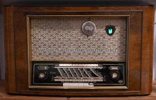
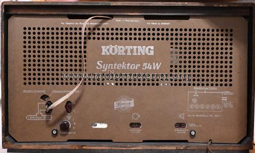
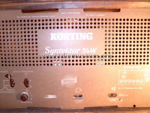
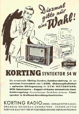
Syntektor 54W
Körting-Radio; Leipzig, später Grassau
- País
- Alemania
- Fabricante / Marca
- Körting-Radio; Leipzig, später Grassau
- Año
- 1953/1954
- Categoría
- Radio - o Sintonizador pasado WW2
- Radiomuseum.org ID
- 19364
-
- alternative name: Dietz & Ritter GmbH, Dr.


ebay, Anbieter: superbenno47
ebay, Anbieter: superbenno47
ebay, Anbieter: superbenno47
ebay, Anbieter: superbenno47
ebay, Anbieter: superbenno47

Gerät aus ebay Auktion
ebay verkäufer: 321-verkaufsagentur
aus ebay, Verkäufer = radiofreunde


Q: Katalog RF-Großhandel 1953/54
Q: Funkschau Info, 15/1953, S288

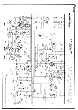
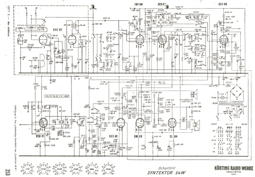
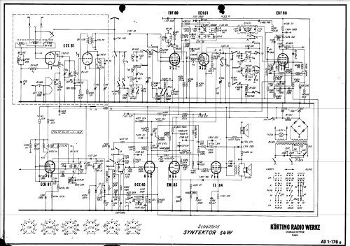
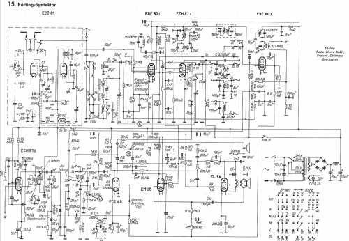
Haga clic en la miniatura esquemática para solicitarlo como documento gratuito.
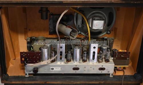
- Numero de valvulas
- 8
- Numero de transistores
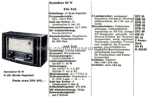
- Principio principal
- Superheterodino con paso previo de RF; ZF/IF 472/10700 kHz
- Número de circuitos sintonía
- 7 Circuíto(s) AM 15 Circuíto(s) FM
- Gama de ondas
- OM, OL, OC y FM
- Tensión de funcionamiento
- Red: Corriente alterna (CA, Inglés = AC) / 110; 125; 220; 240 Volt
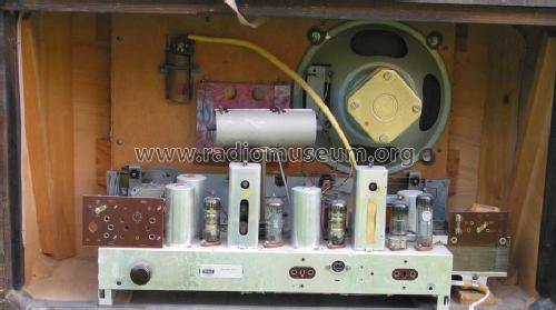
- Altavoz
- 2 Altavoces / Ø 21 cm = 8.3 inch
- Potencia de salida
- 5.7 W (max.)
- Material
- Madera
- de Radiomuseum.org
- Modelo: Syntektor 54W - Körting-Radio; Leipzig, später
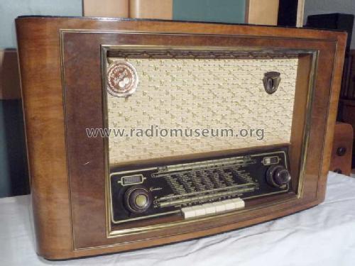
- Forma
- Sobremesa de botonera.
- Ancho, altura, profundidad
- 646 x 390 x 275 mm / 25.4 x 15.4 x 10.8 inch
- Anotaciones
-
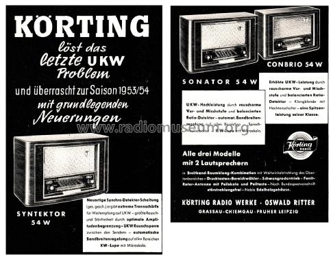
Dr. Ing. Waldemar Moortgat-Pick ist gemäss FG/141/30 der Vater des Körting Syntektor 54 und Royal Syntektor 55 - und natürlich für alle Geräte mit dieser interessanten Schaltung.
Syntektor = Synchro-Detektor (Synchron-Demodulator für UKW-FM).
- Peso neto
- 14.6 kg / 32 lb 2.5 oz (32.159 lb)
- Precio durante el primer año
- 468.00 DM
- Ext. procedencia de los datos
- Erb
- Procedencia de los datos
- Kat.d.Rundf.GrossH.1953/54
- Mencionado en
- -- Original-techn. papers.
- Documentación / Esquemas (1)
- Funkgeschichte der GFGF (Nr.141, p.30)
- Documentación / Esquemas (2)
- Radio-Mentor (5/1954, S.249ff., Empfänger-Test)
- Otros modelos
-
Donde encontrará 822 modelos, 675 con imágenes y 473 con esquemas.
Ir al listado general de Körting-Radio; Leipzig, später Grassau
Colecciones
El modelo Syntektor es parte de las colecciones de los siguientes miembros.
Literatura
El modelo Syntektor está documentado en la siguiente literatura.
Contribuciones en el Foro acerca de este modelo: Körting-Radio;: Syntektor 54W
Hilos: 2 | Mensajes: 4
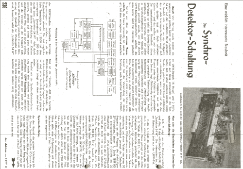
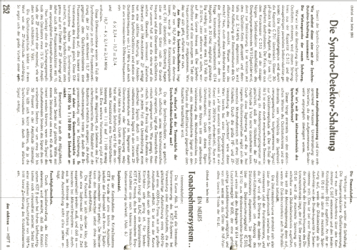
Zu den Synchro-Detektor-Schaltungen der Körting Syntektor Geräte erschienen Berichte in verschiedenen Fachzeitschriften. Hier nun eine Beschreibung des Syntektor 54 nach Unterlagen des Körting Labors.
Der Bericht (2 Seiten + Schaltbild) erschien in Heft 9/1953 der Zeitschrift 'Radio Magazin' und ist dort abgelegt.
Franz Harder, 21.Feb.18
Greetings Fellow Collectors!
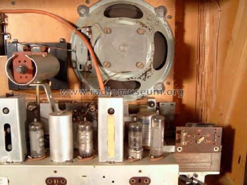
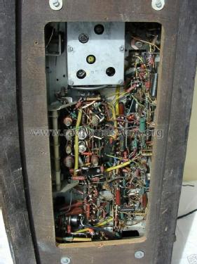
I am fortunate to be in the process of restoring an example of this somewhat historic and technically interesting model from the manufacturer Körting.
After extensive routine work (cleaning, the restuffing of all paper capacitors, etc. etc.) and a complete realignment, I found the UKW to be exemplary in performance, but the LW/MW/KW bands had rather dismal performance at best.
Knowing this model possesses a broadband (untuned) R.F. amplifier stage, I thought that its poorer than average AM performance was quite unusual, especially with the MW band.
I proceeded to trace and investigate a cause.....Was it possibly a mistake in work by myself, or a hidden defect I had overlooked in the resto process?
After a period of time poring over the schematic, taking passive and dynamic measurements and jotting notes,---I discovered the root cause.
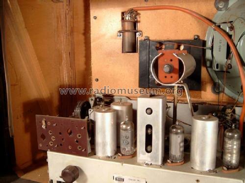
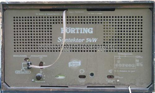
A mistake in switchboard bus wiring had been made during assembly at the factory!
A ground lead was connected to the wrong bus. (39)
No direct ground return was provided for bus (40)
Apparently, these wiring errors were somewhat compensated for at the factory by (mis-) alignment and in doing so, must have allowed this particular unit to pass quality control/ testing.
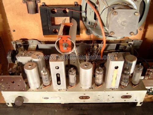
Simply moving the misplaced bus one row to the left side of the tasten Pertinax switchboard and adding the missing 1K resistor,(39 bis 39a,) together with a total realignment of the AM R.F. circuits made for a pleasing surprise of a radio that performs very well!
Please note!
Herr Staginnus has informed me that there are two variants of this model, as noted in the model page data list, schematics "c" and "d." (sch1, sch2) So, my example may not use the 1K cathode resistor switched into the EBF80 (1) cathode circuit for LW band only. (39-39a) I shall remove this resistor I had placed and revert back to direct bus connection per schematic "d," as I found it.
My radio did have the (40) bus/ ground wiring error as mentioned. Sorry for any confusion, and thanks to Herr Staginnus for this observation. We learn!
This radio is certainly worthy now of the installation of a new EM85 indicator tube!
Of little technical use, but this is the first radio that I have literally restuffed the housings of the original Germanium diodes (discriminator) with matched, modern units (NTE110MP)
I type this note as a hint to other owners of the model 54W in the event my radio was not the only example allowed to escape the factory of Körting with this error in bus wiring.
Regards,
D. Daly
Dennis Daly, 28.Sep.08