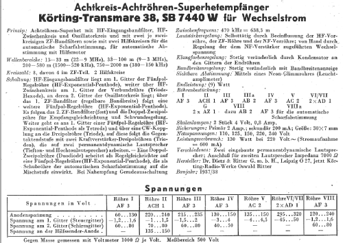
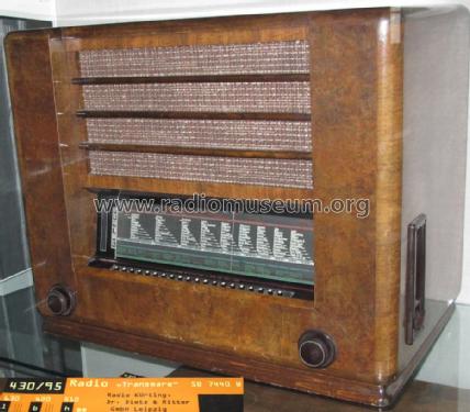
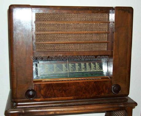
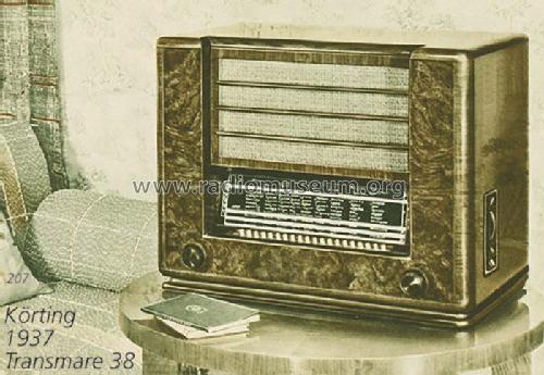
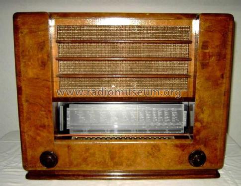
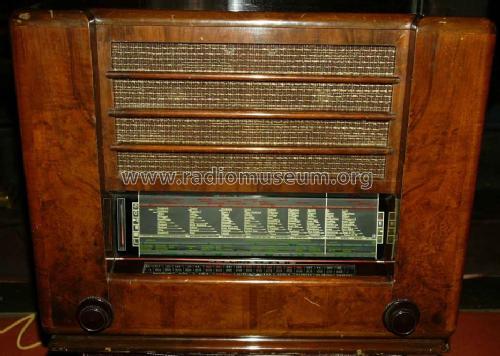
Transmare 38 SB7440W
Körting-Radio; Leipzig, später Grassau
- Paese
- Germania
- Produttore / Marca
- Körting-Radio; Leipzig, später Grassau
- Anno
- 1937/1938
- Categoria
- Radio (o sintonizzatore del dopoguerra WW2)
- Radiomuseum.org ID
- 2460
-
- alternative name: Dietz & Ritter GmbH, Dr.


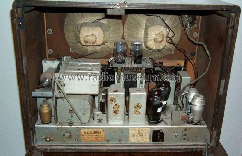
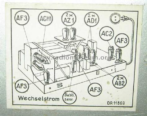
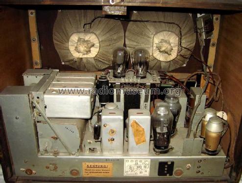
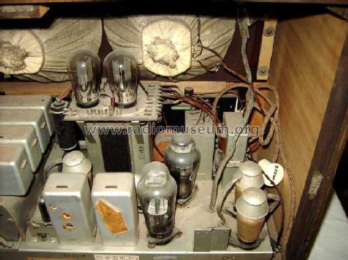
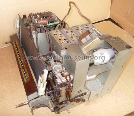
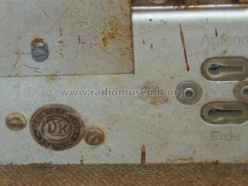
Röhrenabdeckung links oben abgenommen.

ebay 6516986842

ebay 6516986842

ebay 6516986842
ebay 6516986842
ebay 6516986842
ebay 6516986842
ebay 6516986842
ebay 6516986842
ebay 6516986842

ebay 6516986842


Q: Radio-Katalog W.Reuter 1937/38
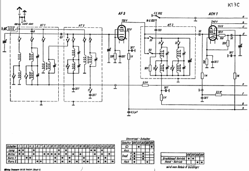
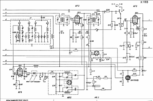
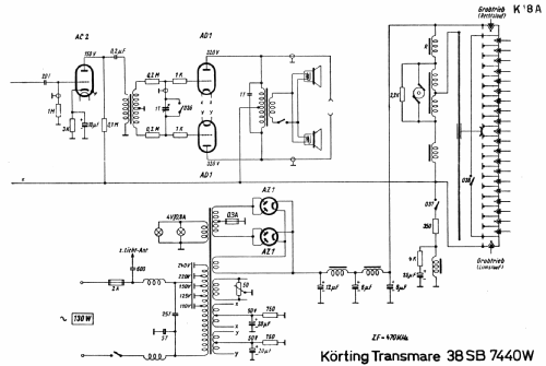
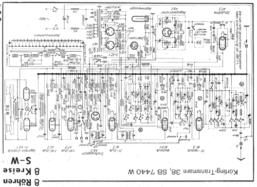
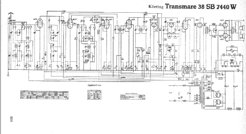
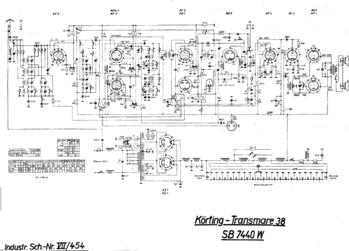
Clicca sulla miniatura dello schema per richiederlo come documento gratuito.
- Numero di tubi
- 12
- Principio generale
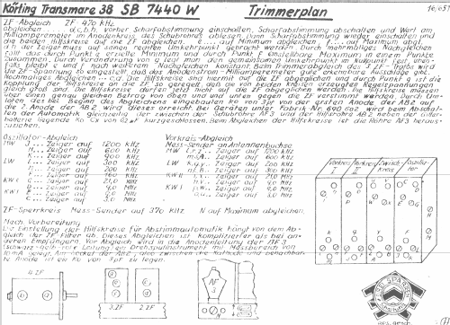
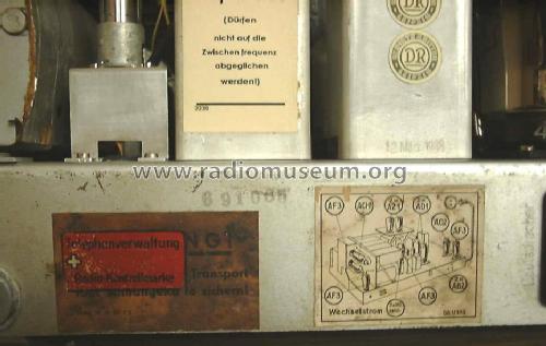
- Supereterodina con stadio RF; ZF/IF 468 or 470 kHz
- N. di circuiti accordati
- 8 Circuiti Mod. Amp. (AM)
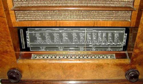
- Gamme d'onda
- Onde medie (OM), lunghe (OL) e 2 onde corte (2 x OC).
- Tensioni di funzionamento
- Alimentazione a corrente alternata (CA) / 110; 125; 150; 220; 240 & 3 Volt
- Altoparlante
- 2 altoparlanti
- Materiali
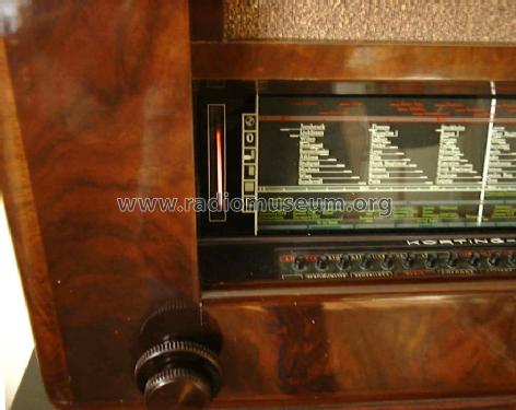
- Mobile in legno
- Radiomuseum.org
- Modello: Transmare 38 SB7440W - Körting-Radio; Leipzig, später
- Forma
- Soprammobile basso, con andamento orizzontale (grosse dimensioni).
- Dimensioni (LxAxP)
- 630 x 500 x 370 mm / 24.8 x 19.7 x 14.6 inch
- Annotazioni
-
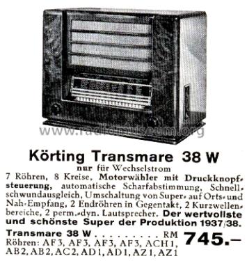
Motorantrieb. AFC. 20 Stationstasten. Variable BBR. Umschaltbar zwischen Super- und Geradeausempfänger. Mit Spannungsstabilisator DR 11551/2. Gitter-Batterie Pertrix 259.
Die erste Fabrikationsserie war auf die ZF von 468 kHz eingestellt.
- Peso netto
- 37 kg / 81 lb 8 oz (81.498 lb)
- Prezzo nel primo anno
- 745.00 RM
- Fonte dei dati
- Handbuch WDRG 1937 / Radiokatalog Band 1, Ernst Erb
- Riferimenti schemi
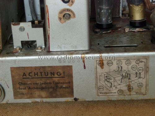
- Lange+Schenk+FS-Röhrenbestückung
- Bibliografia
- Historische Radios (1-5) = zur Verknüpfung mit Modellseiten (Körting Jahrbuch 1938 für Elektroakustik)
- Bibliografia immagini
- Das Modell ist im «Radiokatalog» (Erb) abgebildet.
- Altri modelli
-
In questo link sono elencati 825 modelli, di cui 678 con immagini e 473 con schemi.
Elenco delle radio e altri apparecchi della Körting-Radio; Leipzig, später Grassau
Collezioni
Il modello Transmare 38 fa parte delle collezioni dei seguenti membri.
Musei
Il modello Transmare 38 può essere visto nei seguenti musei.
Discussioni nel forum su questo modello: Körting-Radio;: Transmare 38 SB7440W
Argomenti: 2 | Articoli: 4
I am restoring a transmare 38.
The set uses a voltage regulator tube. It was not present. From information I collected, it is a 150 Volts gas regulator.
For the time being it was replaced by an OA2.
I will apretiate information on this regulator (Number and specs.) and the possibility to find one of them.
Also very interested to interchange opinions on this model.
Jose
New august 20 2004
I finished the chassis. It is working fine in all functions.The case has been restored too.
The following list is of items needed to complete the restoration:
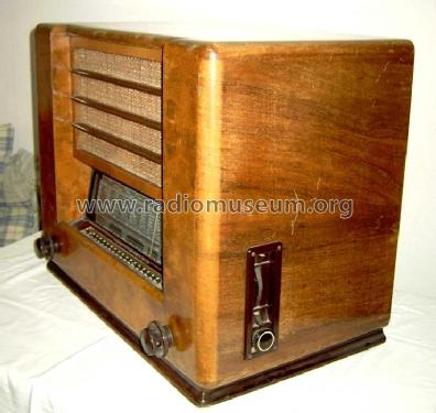
1. Rear view to reproduce the rear cover which is missing.
2. View of the speaker switch wich is broken, to reproduce the original shape.
3. The knob that controls the function of preselected radio stations. Missing
4. The regulating valve. Is a 150 Volts bayonet socket. (similar in specifications to the OA2)
Any help will be apretiated.
Jose
Allegati
- Hilfskreise (50 KB)
Jose Vigil, 28.Jun.04
Jose Vigil, 30.Oct.02