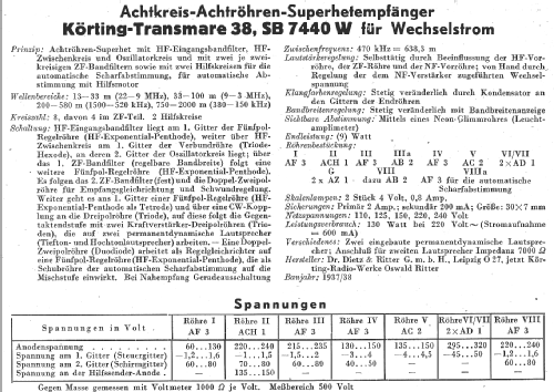
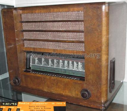
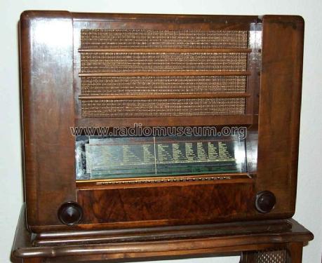
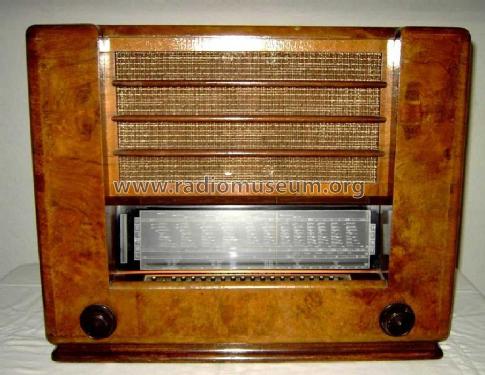
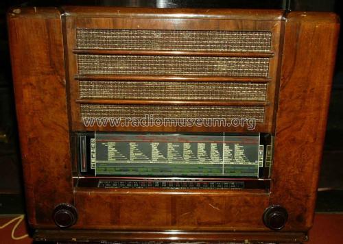
Transmare 38 SB7440W
Körting-Radio; Leipzig, später Grassau
- Hersteller / Marke
- Körting-Radio; Leipzig, später Grassau
- Jahr
- 1937/1938
- Kategorie
- Rundfunkempfänger (Radio - oder Tuner nach WW2)
- Radiomuseum.org ID
- 2460
-
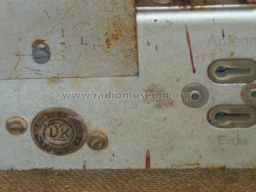
- anderer Name: Dietz & Ritter GmbH, Dr.


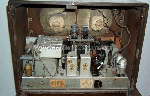
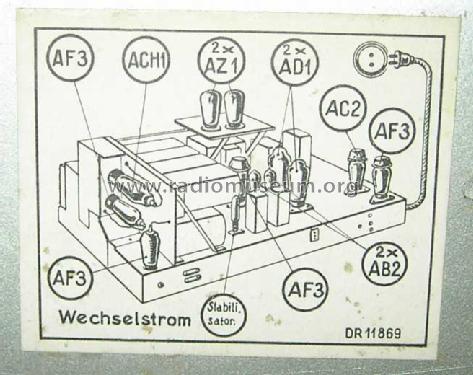
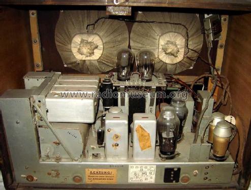
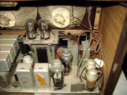
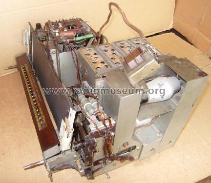
Röhrenabdeckung links oben abgenommen.

ebay 6516986842

ebay 6516986842

ebay 6516986842
ebay 6516986842
ebay 6516986842
ebay 6516986842
ebay 6516986842
ebay 6516986842
ebay 6516986842

ebay 6516986842


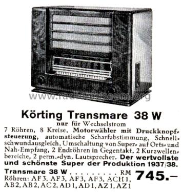
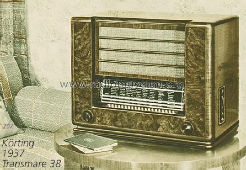
Q: Radio-Katalog W.Reuter 1937/38
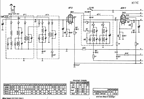
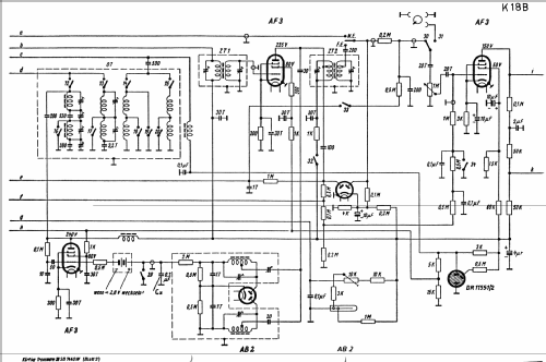
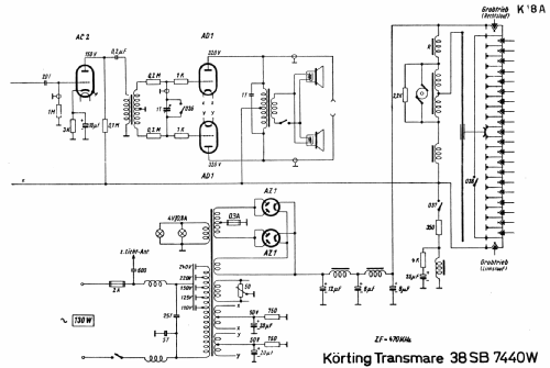
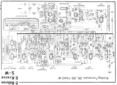
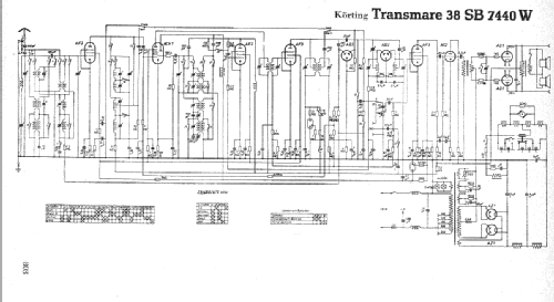
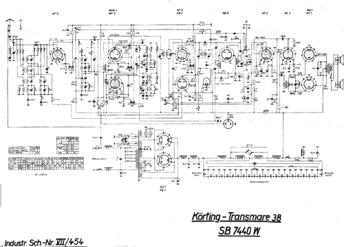
Klicken Sie auf den Schaltplanausschnitt, um diesen kostenlos als Dokument anzufordern.
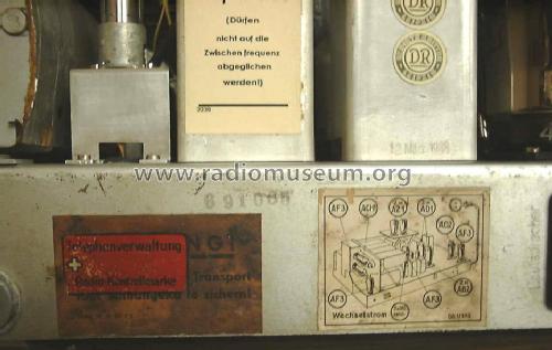
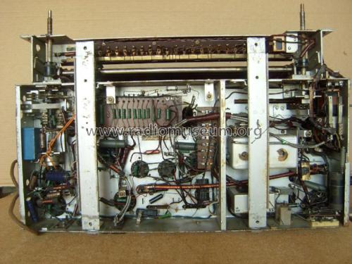
- Anzahl Röhren
- 12
- Hauptprinzip
- Super mit HF-Vorstufe; ZF/IF 468 or 470 kHz
- Anzahl Kreise
- 8 Kreis(e) AM
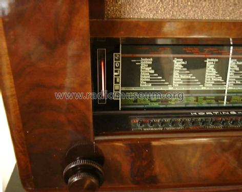
- Wellenbereiche
- Langwelle, Mittelwelle und zwei mal Kurzwelle.
- Betriebsart / Volt
- Wechselstromspeisung / 110; 125; 150; 220; 240 & 3 Volt
- Lautsprecher
- 2 Lautsprecher
- Material
- Gerät mit Holzgehäuse
- von Radiomuseum.org
- Modell: Transmare 38 SB7440W - Körting-Radio; Leipzig, später
- Form
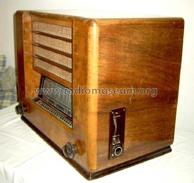
- Tischgerät-gross, - Querformat (breiter als hoch oder quadratisch).
- Abmessungen (BHT)
- 630 x 500 x 370 mm / 24.8 x 19.7 x 14.6 inch
- Bemerkung
-
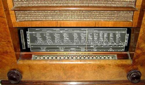
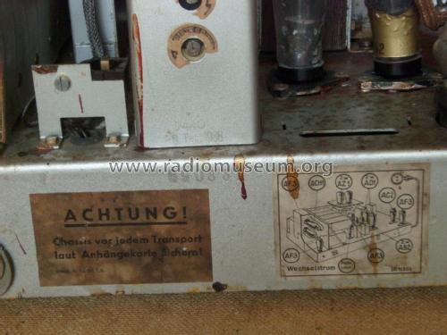
Motorantrieb. AFC. 20 Stationstasten. Variable BBR. Umschaltbar zwischen Super- und Geradeausempfänger. Mit Spannungsstabilisator DR 11551/2. Gitter-Batterie Pertrix 259.
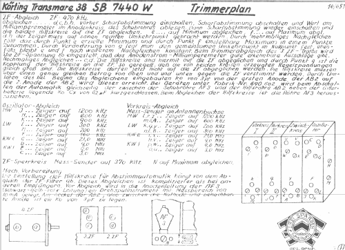
Die erste Fabrikationsserie war auf die ZF von 468 kHz eingestellt.
- Nettogewicht
- 37 kg / 81 lb 8 oz (81.498 lb)
- Originalpreis
- 745.00 RM
- Datenherkunft
- Handbuch WDRG 1937 / Radiokatalog Band 1, Ernst Erb
- Schaltungsnachweis
- Lange+Schenk+FS-Röhrenbestückung
- Literaturnachweis
- Historische Radios (1-5) = zur Verknüpfung mit Modellseiten (Körting Jahrbuch 1938 für Elektroakustik)
- Bildnachweis
- Das Modell ist im «Radiokatalog» (Erb) abgebildet.
- Weitere Modelle
-
Hier finden Sie 825 Modelle, davon 678 mit Bildern und 473 mit Schaltbildern.
Alle gelisteten Radios usw. von Körting-Radio; Leipzig, später Grassau
Sammlungen
Das Modell Transmare 38 befindet sich in den Sammlungen folgender Mitglieder.
Museen
Das Modell Transmare 38 ist in den folgenden Museen zu sehen.
Forumsbeiträge zum Modell: Körting-Radio;: Transmare 38 SB7440W
Threads: 2 | Posts: 4
I am restoring a transmare 38.
The set uses a voltage regulator tube. It was not present. From information I collected, it is a 150 Volts gas regulator.
For the time being it was replaced by an OA2.
I will apretiate information on this regulator (Number and specs.) and the possibility to find one of them.
Also very interested to interchange opinions on this model.
Jose
New august 20 2004
I finished the chassis. It is working fine in all functions.The case has been restored too.
The following list is of items needed to complete the restoration:
1. Rear view to reproduce the rear cover which is missing.
2. View of the speaker switch wich is broken, to reproduce the original shape.
3. The knob that controls the function of preselected radio stations. Missing
4. The regulating valve. Is a 150 Volts bayonet socket. (similar in specifications to the OA2)
Any help will be apretiated.
Jose
Anlagen
- Hilfskreise (50 KB)
Jose Vigil, 28.Jun.04
Jose Vigil, 30.Oct.02