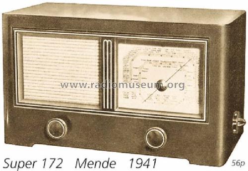
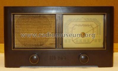
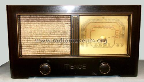
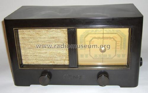
MS172-W (172W)
Mende - Radio H. Mende & Co. GmbH, Dresden
- Pays
- Allemagne
- Fabricant / Marque
- Mende - Radio H. Mende & Co. GmbH, Dresden
- Année
- 1941–1943
- Catégorie
- Radio - ou tuner d'après la guerre 1939-45
- Radiomuseum.org ID
- 3647
-
- Brand: System Günther


ebay 6600551067

ebay 6600551067
ebay 6600551067
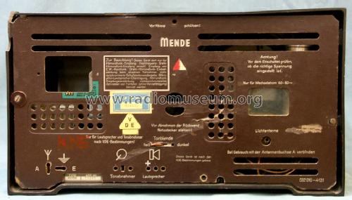


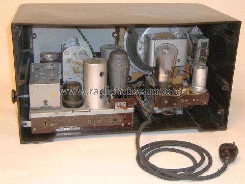
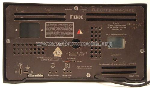

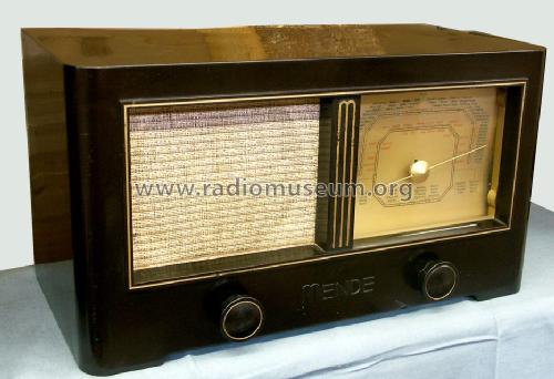
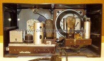
Mende 172W back view
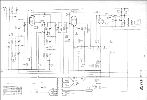
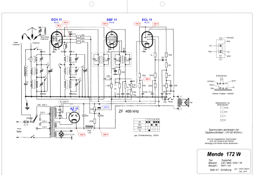
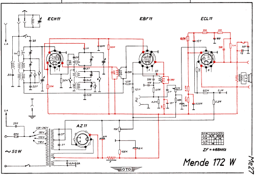
Cliquez sur la vignette du schéma pour le demander en tant que document gratuit.
- No. de tubes
- 4
- Principe général
- Super hétérodyne (en général); FI/IF 468 kHz
- Circuits accordés
- 6 Circuits MA (AM)
- Gammes d'ondes
- PO, GO et OC
- Tension / type courant
- Alimentation Courant Alternatif (CA) / 110-240 Volt
- Haut-parleur
- HP dynamique à électro-aimant (électrodynamique)
- Matière
- Boitier en bakélite
- De Radiomuseum.org
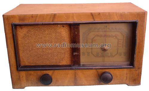
- Modèle: MS172-W - Mende - Radio H. Mende & Co.
- Forme
- Modèle de table générique
- Dimensions (LHP)
- 420 x 235 x 210 mm / 16.5 x 9.3 x 8.3 inch
- Remarques
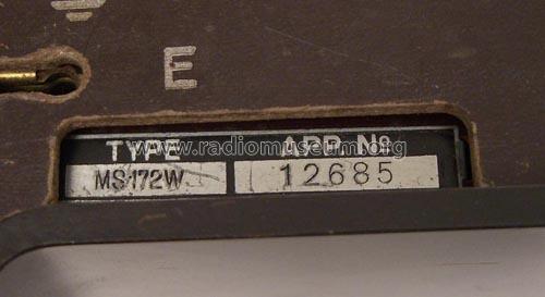
- Das Typschild des Empfängers zeigt MS172-W, dagegen führen die Service-Unterlagen die Typbezeichnung 172W.
Es handelt sich dabei um dasselbe Modell.
- Poids net
- 9 kg / 19 lb 13.2 oz (19.824 lb)
- Source
- Radiokatalog Band 1, Ernst Erb
- Source du schéma
- Lange+Schenk+FS-Röhrenbestückung
- Littérature
- Funkgeschichte der GFGF (9284)
- Index des illustrations
- Das Modell ist im «Radiokatalog» (Erb) abgebildet.
- D'autres Modèles
-
Vous pourrez trouver sous ce lien 317 modèles d'appareils, 284 avec des images et 207 avec des schémas.
Tous les appareils de Mende - Radio H. Mende & Co. GmbH, Dresden
Collections
Le modèle fait partie des collections des membres suivants.
Contributions du forum pour ce modèle: Mende - Radio H.: MS172-W
Discussions: 2 | Publications: 7
Hallo Sammlerfreunde,
ich möchte mal wieder auf einen Fehler im Schaltplan hinweisen. Die Gegenkopplung von der ECL 11 rechts oben im ersten Schaltplan ist falsch gezeichnet. Das betrifft leider auch den Plan im Empfänger Vade-Mecum S.995 . Die beiden anderen Schaltpläne im RM kann ich nicht beurteilen, da ich sie mir aus bekannten Gründen nicht heruntergeladen habe und die Quelle nicht kenne.
Herzliche Grüße
M. Böhme
Mario Böhme, 04.Dec.14
Greetings!
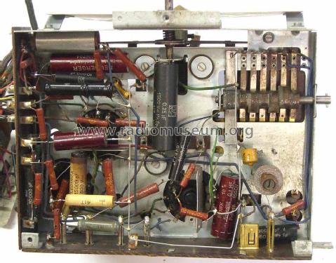
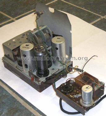
I have one of these Mende 172W radios in which the speaker has been disconnected. I am having trouble understanding the connections to the field coil.
There are 4 connections and four wires going to the field.
In the picture below, I have numbered the connections.
Between 1 and 2, I measure. 3.4 K ohms. Also 3.4 K ohms between points 3 and 4. So it seems that there are 2 windings in the field. There is no connection between the 2 fields.
Between points 5 and 6 measures 600 ohms, so that is the primary of the speaker transformer. No problem there.
Can anyone explain to me why there are these 2 fields and how they should be connected up? The schematic diagram gives a measurement of 1500 Ohms for the field.
Is it that the fields should be connected in parallel?
Sorry, but my German is not quite good enough to explain this problem.
Thanks
Peter
Pièces jointes
- Mende speaker (118 KB)
- Mende speaker 1 (119 KB)
Peter Hughes, 23.May.14