K42N Diverse Umbauten
Nora, Aron, Heliowatt; Berlin
- Paese
- Germania
- Produttore / Marca
- Nora, Aron, Heliowatt; Berlin
- Anno
- 1942–1944
- Categoria
- Radio (o sintonizzatore del dopoguerra WW2)
- Radiomuseum.org ID
- 94694


Clicca sulla miniatura dello schema per richiederlo come documento gratuito.
- Numero di tubi
- 5
- Principio generale
- Supereterodina (in generale)
- N. di circuiti accordati
- 4 Circuiti Mod. Amp. (AM)
- Gamme d'onda
- Onde medie (OM), lunghe (OL) e corte (OC).
- Tensioni di funzionamento
- Rete / Batterie di accumulatori (eventualmente anche le batterie) / 120; 150; 220; 240 / 2 & 90 Volt
- Altoparlante
- AP magnetodinamico (magnete permanente e bobina mobile) / Ø 12 cm = 4.7 inch
- Materiali
- Mobile in legno
- Radiomuseum.org
- Modello: K42N [Diverse Umbauten] - Nora, Aron, Heliowatt; Berlin
- Forma
- Apparecchio portatile > 20 cm (senza la necessità di una rete)
- Dimensioni (LxAxP)
- 480 x 275 x 115 mm / 18.9 x 10.8 x 4.5 inch
- Annotazioni
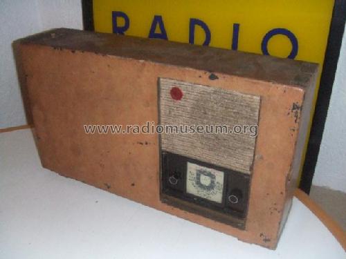
- Wehrmacht-Truppenbetreuungsempfänger? Anderes Gehäuse als die anderern K42.
- Fonte dei dati
- - - Data from my own collection
- Letteratura / Schemi (1)
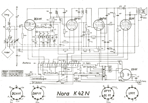
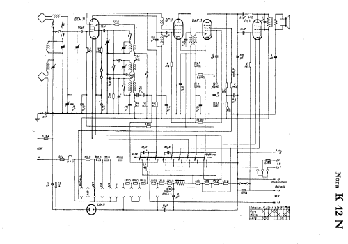
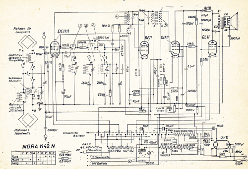
- -- Schematic
- Autore
- Modello inviato da Reinhard Hanschke. Utilizzare "Proponi modifica" per inviare ulteriori dati.
- Altri modelli
-
In questo link sono elencati 634 modelli, di cui 557 con immagini e 343 con schemi.
Elenco delle radio e altri apparecchi della Nora, Aron, Heliowatt; Berlin
Collezioni
Il modello fa parte delle collezioni dei seguenti membri.
Discussioni nel forum su questo modello: Nora, Aron,: K42N
Argomenti: 3 | Articoli: 13
I recently acquired a Nora k42n of which I cannot find any information. First, this radio is equipped with 6 tubes: Visseaux 6C5 metal tube, Valvo 6L7, Valvo 6F7, 6H7?(may be a different number), Valvo89 and a Valvo 89 in the power supply. 5 out of the 6 tubes are glass tubes with the heater connection on top of each. The radio is AC mains only. The speaker grill is on top and the glass dial on the bottom to accomidate the length of the Valvo tubes I can't find a power switch unless the volume control is also the on/off switch. There are no schematic, labels or tube layouts on the case or back, but there is evidence of them at one time. So my problem is I don't know if the tubes are correct for this radio or in a different order. The radio looks like it was factory made and it was neatly done. I am guessing that this radio was a either a prototype or it was assembled near the end of the war with anything that was available. Since it has 6 tubes in it I'm thinking it was an early model or one designated for a location that was easy on glass tubes, or metal tubes were not yet available. Somewhere it was painted an ugly green color over the original dark grey.I found a match for the original grey and I will return the radio to it's former condition. I would like to restore this radio to at least the proper tube positions( meaning I want to still use the glass tubes) I will settle for a display only piece, but it would be nice to have it play. I am not versed in wiring and electrical repair. I have a fellow collector that is my savior. I however do the wood restorations rather well. Any information or guidence will be a big help to me Thank you.
Garrett Walsh, 05.Jul.11
Bernd Schmitz, 26.Apr.08
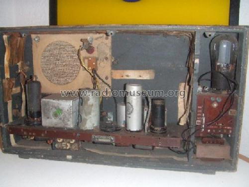
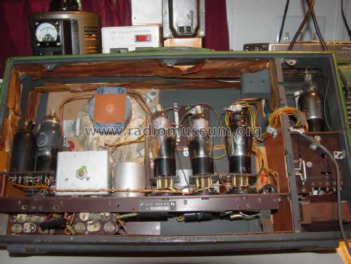
Anstelle der Gleichrichterröhre UY 11 (in K 42 N), wurde eine AZ 1 von TELEFUNKEN, nach entsprechendem Umbau, verwendet. Der Röhrensockel konnte verbleiben, da identisch. Neue Röhrensockel bedurfte es für den Ersatz der DAF 11 und der DL 11. Hier wurden eine VALVO (6K7MG) und eine RCA (VT? SC 278 A - "Made in U.S.A") verwendet. Für die DCH 11 kam nach entsprechender Sockelumpolung eine unbekannte italienische Röhre mit einer italienischen Steuerbanderole (MINISTERO DELLE FINANZE) vom 27. Nov. 1942 zur Verwendung. Auch wurde ein Bandfilter ausgewechselt.
Nachdem die ausgetauschten Röhren sowie das eine Bandfilter höher sind als die Stahlröhren, bzw. das Bandfilter, wurde seinerzeit das Chassis von oben nach unten verlegt. Dazu wurde links und rechts in das Holzgehäuse eine neue Fuge (hier kein Farbanstrich) angebracht, in die nun das Chassis eingeschoben werden konnte. Folglich musste aber auch der Lautsprecher von unten nach oben versetzt werden.
Die Belüftung der AZ 1 erfolgt mittels metallenen Lüftungsschlitzen oberhalb und seitlich rechts von dieser Röhre. Als "eingebaute" Antenne wirkten zwei zweiadrige Drähte um den Innenraum des Gehäuses herum, verdeckt von einem Papier-Klebestreife, so wie auch beim K 42.
Leider fehlt bei diesem Modell die Rückwand, der Lautsprecher und das abgezwickte Netzkabel.
Aus der Gesamtschau heraus gesehen ist dieses Modell ein kleiner historischer Beleg über die Leistungs- und Leidensfähigkeit des Fernmelders in der Deutschen Wehrmacht.
Hanschke Reinhard
Reinhard Hanschke, 15.Apr.06