- Country
- Great Britain (UK)
- Manufacturer / Brand
- Philips Electrical, Lamps, Industrial - Miniwatt; London
- Year
- 1949
- Category
- Broadcast Receiver - or past WW2 Tuner
- Radiomuseum.org ID
- 143931


Click on the schematic thumbnail to request the schematic as a free document.
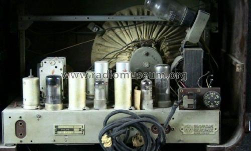
- Number of Tubes
- 5
- Main principle
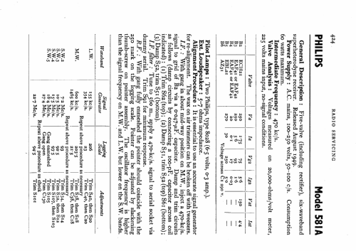
- Superheterodyne (common); ZF/IF 470 kHz; 2 AF stage(s)
- Tuned circuits
- 6 AM circuit(s)
- Wave bands
- Broadcast, Long Wave and more than two Short Wave bands.
- Power type and voltage
- Alternating Current supply (AC) / 100-250 Volt
- Loudspeaker
- Permanent Magnet Dynamic (PDyn) Loudspeaker (moving coil)
- Material
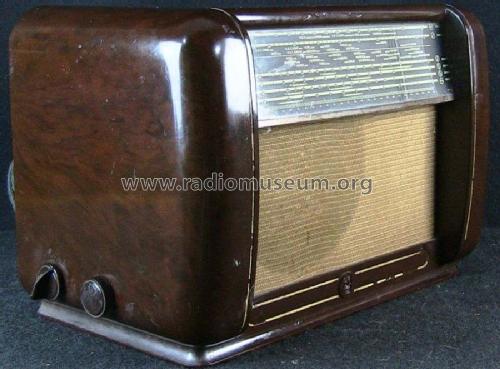
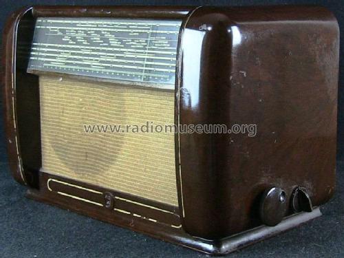
- Bakelite case
- from Radiomuseum.org
- Model: 581A - Philips Electrical, Lamps,
- Shape
- Tablemodel, low profile (big size).
- Notes
- 6 wavebands (4 SW bands).
- Source of data
- -- Schematic
- Literature/Schematics (1)
- Radio And Television Servicing books (R&TVS)
- Author
- Model page created by Keith Staines. See "Data change" for further contributors.
- Other Models
-
Here you find 427 models, 305 with images and 286 with schematics for wireless sets etc. In French: TSF for Télégraphie sans fil.
All listed radios etc. from Philips Electrical, Lamps, Industrial - Miniwatt; London
Forum contributions about this model: Philips Electrical,: 581A
Threads: 1 | Posts: 3
I am repairing a Philips radio 581A/15. The radio has been previously worked on and has a hole in the chassis where an electrolytic was once located.
Was this hole for a second 50 mf capacitor or for C3, 25 mf capacitor. Does anyone have this radio that can tell me where C3 (25mf) should be located?
There is presently a single can type electrolytic housing two 50 mf capacitors on top of chassis. Is this original or were there two single 50 mf caps.
Also, also what do the numbers on the old black capacitors represent, pico farads? Most are faded away and difficult to read.
Although my model is a 581A/15 the schematic for the 581A/15 seems to be appropriate. Research implies that this is the same or similar chassis to the Mullard MAS225.
Thank you in advance for your help.
Vince Cappuccitti
Vincent Cappuccitti, 08.Feb.20