- Produttore / Marca
- Philips Electrical, Lamps, Industrial - Miniwatt; London
- Anno
- 1949
- Categoria
- Radio (o sintonizzatore del dopoguerra WW2)
- Radiomuseum.org ID
- 143931


Clicca sulla miniatura dello schema per richiederlo come documento gratuito.
- Numero di tubi
- 5
- Principio generale
- Supereterodina (in generale); ZF/IF 470 kHz; 2 Stadi BF
- N. di circuiti accordati
- 6 Circuiti Mod. Amp. (AM)
- Gamme d'onda
- Onde medie (OM), lunghe (OL) e più di 2 gamme di onde corte (>2 x OC).
- Tensioni di funzionamento
- Alimentazione a corrente alternata (CA) / 100-250 Volt
- Altoparlante
- AP magnetodinamico (magnete permanente e bobina mobile)
- Materiali
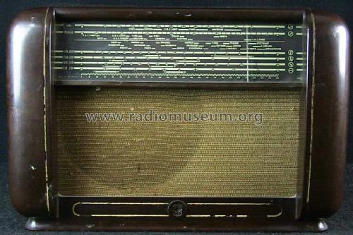
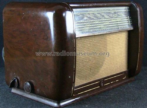
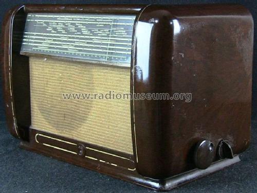
- Bachelite
- Radiomuseum.org
- Modello: 581A - Philips Electrical, Lamps,
- Forma
- Soprammobile basso, con andamento orizzontale (grosse dimensioni).
- Annotazioni
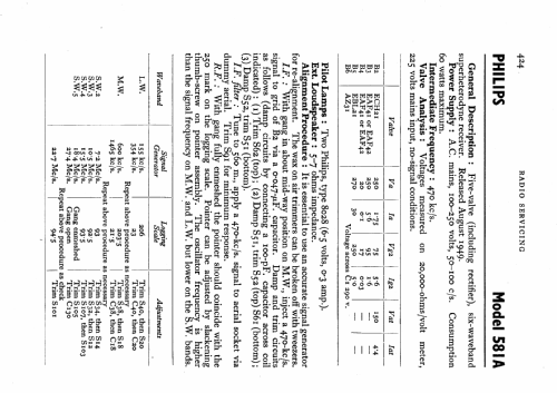
- 6 wavebands (4 SW bands).
- Fonte dei dati
- -- Schematic
- Letteratura / Schemi (1)
- Radio And Television Servicing books (R&TVS)
- Autore
- Modello inviato da Keith Staines. Utilizzare "Proponi modifica" per inviare ulteriori dati.
- Altri modelli
-
In questo link sono elencati 427 modelli, di cui 305 con immagini e 286 con schemi.
Elenco delle radio e altri apparecchi della Philips Electrical, Lamps, Industrial - Miniwatt; London
Discussioni nel forum su questo modello: Philips Electrical,: 581A
Argomenti: 1 | Articoli: 3
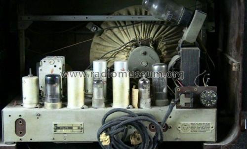
I am repairing a Philips radio 581A/15. The radio has been previously worked on and has a hole in the chassis where an electrolytic was once located.
Was this hole for a second 50 mf capacitor or for C3, 25 mf capacitor. Does anyone have this radio that can tell me where C3 (25mf) should be located?
There is presently a single can type electrolytic housing two 50 mf capacitors on top of chassis. Is this original or were there two single 50 mf caps.
Also, also what do the numbers on the old black capacitors represent, pico farads? Most are faded away and difficult to read.
Although my model is a 581A/15 the schematic for the 581A/15 seems to be appropriate. Research implies that this is the same or similar chassis to the Mullard MAS225.
Thank you in advance for your help.
Vince Cappuccitti
Vincent Cappuccitti, 08.Feb.20