- Land
- Grossbritannien (UK)
- Hersteller / Marke
- Philips Electrical, Lamps, Industrial - Miniwatt; London
- Jahr
- 1949
- Kategorie
- Rundfunkempfänger (Radio - oder Tuner nach WW2)
- Radiomuseum.org ID
- 143931


Klicken Sie auf den Schaltplanausschnitt, um diesen kostenlos als Dokument anzufordern.
- Anzahl Röhren
- 5
- Hauptprinzip
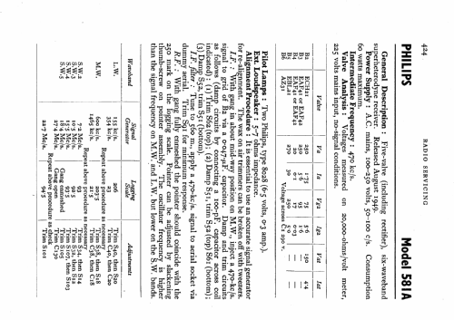
- Superhet allgemein; ZF/IF 470 kHz; 2 NF-Stufe(n)
- Anzahl Kreise
- 6 Kreis(e) AM
- Wellenbereiche
- Langwelle, Mittelwelle und mehrere Kurzwellen-Bänder.
- Betriebsart / Volt
- Wechselstromspeisung / 100-250 Volt
- Lautsprecher
- Dynamischer LS, keine Erregerspule (permanentdynamisch)
- Material
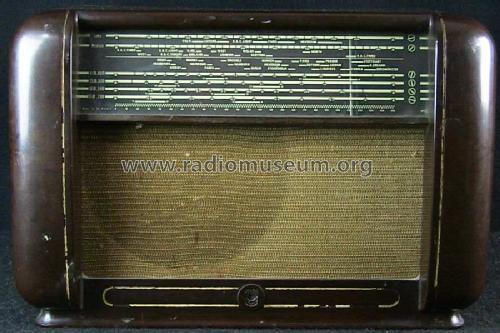
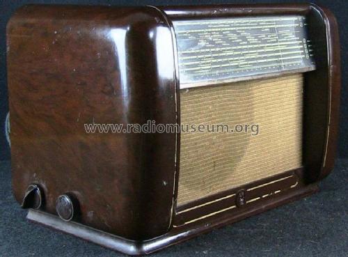
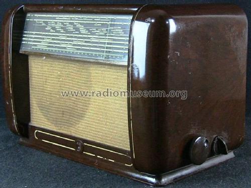
- Bakelit (Pressstoff)
- von Radiomuseum.org
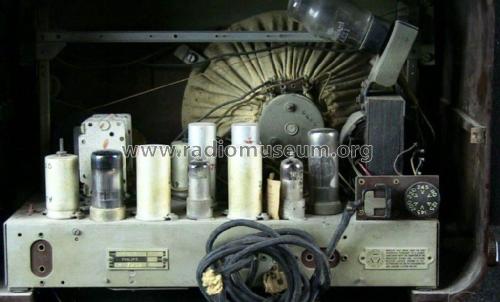
- Modell: 581A - Philips Electrical, Lamps,
- Form
- Tischgerät-gross, - Querformat (breiter als hoch oder quadratisch).
- Bemerkung
- 6 wavebands (4 SW bands).
- Datenherkunft
- -- Schematic
- Literatur/Schema (1)
- Radio And Television Servicing books (R&TVS)
- Autor
- Modellseite von Keith Staines angelegt. Siehe bei "Änderungsvorschlag" für weitere Mitarbeit.
- Weitere Modelle
-
Hier finden Sie 427 Modelle, davon 305 mit Bildern und 286 mit Schaltbildern.
Alle gelisteten Radios usw. von Philips Electrical, Lamps, Industrial - Miniwatt; London
Forumsbeiträge zum Modell: Philips Electrical,: 581A
Threads: 1 | Posts: 3
I am repairing a Philips radio 581A/15. The radio has been previously worked on and has a hole in the chassis where an electrolytic was once located.
Was this hole for a second 50 mf capacitor or for C3, 25 mf capacitor. Does anyone have this radio that can tell me where C3 (25mf) should be located?
There is presently a single can type electrolytic housing two 50 mf capacitors on top of chassis. Is this original or were there two single 50 mf caps.
Also, also what do the numbers on the old black capacitors represent, pico farads? Most are faded away and difficult to read.
Although my model is a 581A/15 the schematic for the 581A/15 seems to be appropriate. Research implies that this is the same or similar chassis to the Mullard MAS225.
Thank you in advance for your help.
Vince Cappuccitti
Vincent Cappuccitti, 08.Feb.20