- Pays
- Royaume Uni
- Fabricant / Marque
- Philips Electrical, Lamps, Industrial - Miniwatt; London
- Année
- 1949
- Catégorie
- Radio - ou tuner d'après la guerre 1939-45
- Radiomuseum.org ID
- 143931


Cliquez sur la vignette du schéma pour le demander en tant que document gratuit.
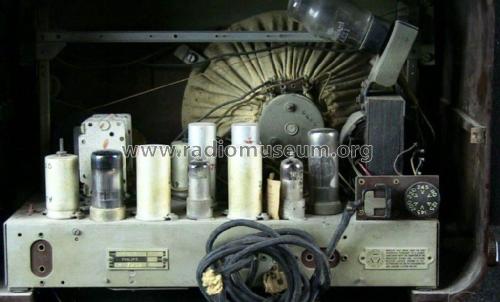
- No. de tubes
- 5
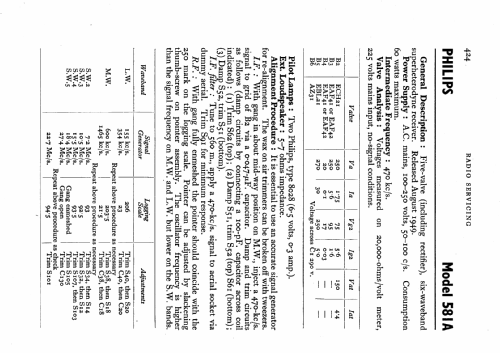
- Principe général
- Super hétérodyne (en général); FI/IF 470 kHz; 2 Etage(s) BF
- Circuits accordés
- 6 Circuits MA (AM)
- Gammes d'ondes
- PO, GO et plus que 2 x OC
- Tension / type courant
- Alimentation Courant Alternatif (CA) / 100-250 Volt
- Haut-parleur
- HP dynamique à aimant permanent + bobine mobile
- Matière
- Boitier en bakélite
- De Radiomuseum.org
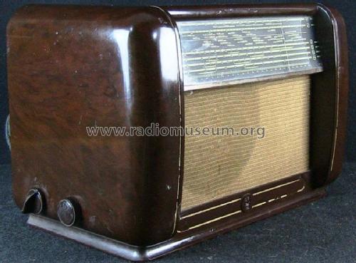
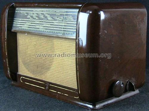
- Modèle: 581A - Philips Electrical, Lamps,
- Forme
- Modèle de table profil bas (grand modèle).
- Remarques
- 6 wavebands (4 SW bands).
- Source
- -- Schematic
- Schémathèque (1)
- Radio And Television Servicing books (R&TVS)
- Auteur
- Modèle crée par Keith Staines. Voir les propositions de modification pour les contributeurs supplémentaires.
- D'autres Modèles
-
Vous pourrez trouver sous ce lien 427 modèles d'appareils, 305 avec des images et 286 avec des schémas.
Tous les appareils de Philips Electrical, Lamps, Industrial - Miniwatt; London
Contributions du forum pour ce modèle: Philips Electrical,: 581A
Discussions: 1 | Publications: 3
I am repairing a Philips radio 581A/15. The radio has been previously worked on and has a hole in the chassis where an electrolytic was once located.
Was this hole for a second 50 mf capacitor or for C3, 25 mf capacitor. Does anyone have this radio that can tell me where C3 (25mf) should be located?
There is presently a single can type electrolytic housing two 50 mf capacitors on top of chassis. Is this original or were there two single 50 mf caps.
Also, also what do the numbers on the old black capacitors represent, pico farads? Most are faded away and difficult to read.
Although my model is a 581A/15 the schematic for the 581A/15 seems to be appropriate. Research implies that this is the same or similar chassis to the Mullard MAS225.
Thank you in advance for your help.
Vince Cappuccitti
Vincent Cappuccitti, 08.Feb.20