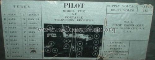
Pilot Candid TV37
Pilot Electric Mfg. Co. (Radio Corp.); Brooklyn (NY)
- País
- Estados Unidos
- Fabricante / Marca
- Pilot Electric Mfg. Co. (Radio Corp.); Brooklyn (NY)
- Año
- 1948 ?

- Categoría
- Televisión (TV) o monitor
- Radiomuseum.org ID
- 91514
-
- alternative name: Pilot Radio & Television || Pilot Radio and Tube || Pilot Radio Corporation


Pilot Electric Mfg.: Candid TV37 - 2
EbayCOM estate_treasurez 6250958284
EbayCOM estate_treasurez 6250958284
EbayCOM estate_treasurez 6250958284
EbayCOM estate_treasurez 6250958284
mon tele TV37U


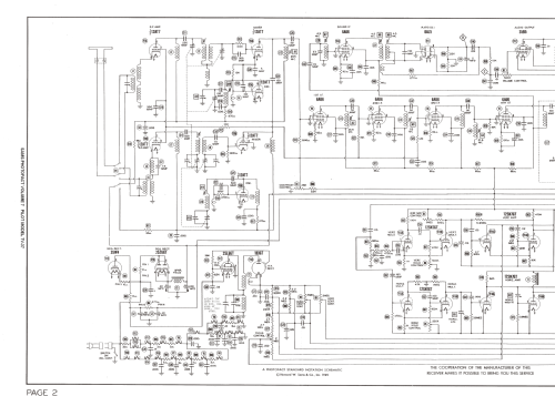
SAMS Photofact Volume 7 4910-16
Pilot Electric Mfg.: Candid TV37 - 1
Pilot Electric Mfg.: Candid TV37 - 3
Pilot Electric Mfg.: Candid TV37 - 4
Pilot Electric Mfg.: Candid TV37 - 5
Pilot Electric Mfg.: Candid TV37 - 6

Pilot Electric Mfg.: Candid TV37 - 7
Pilot Electric Mfg.: Candid TV37 - 8
Pilot Electric Mfg.: Candid TV37 - 9

Pilot Electric Mfg.: Candid TV37 - 10

Pilot Electric Mfg.: Candid TV37 - 11
Pilot Electric Mfg.: Candid TV37 - 12
Pilot Electric Mfg.: Candid TV37 - 13
Pilot Electric Mfg.: Candid TV37 - 14
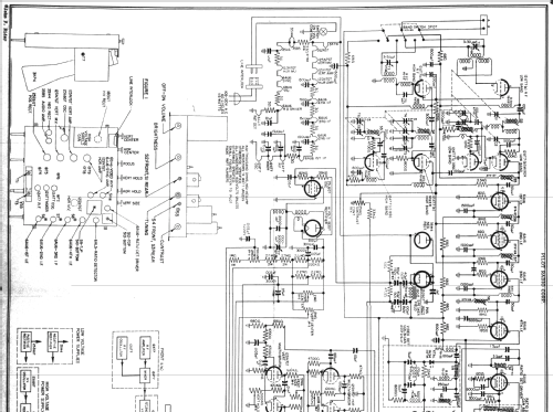
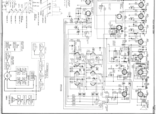
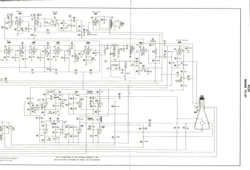
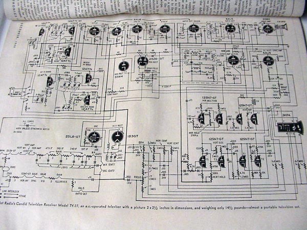
Haga clic en la miniatura esquemática para solicitarlo como documento gratuito.
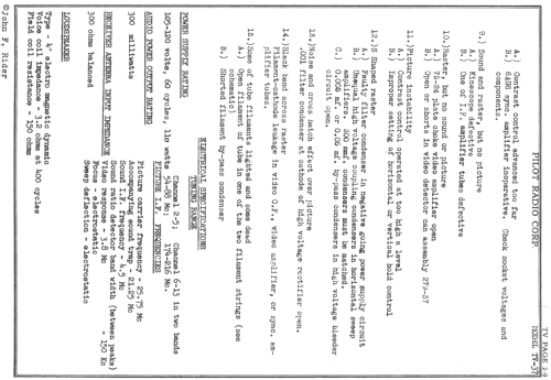
- Numero de valvulas
- 21
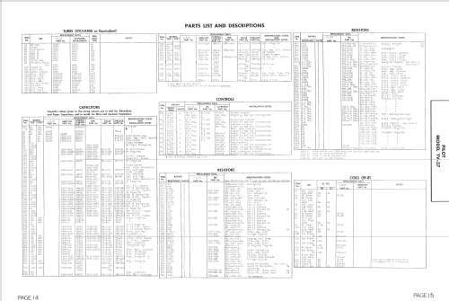
- Válvulas
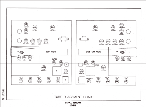
- 3KP4 12AT7 12AT7 12AT7 6AU6 6AU6 6AU6 6AU6 6AU6 6AL5 35B5 6BA6 6AU6 12SN7GT 12SN7GT 12SN7GT 12SN7GT
- Principio principal
- Superheterodino en general
- Gama de ondas
- VHF/UHF (see notes for details)
- Tensión de funcionamiento
- Red: Corriente alterna (CA, Inglés = AC) / 105-120 Volt
- Altavoz
- Altavoz electrodinámico (bobina de campo) / Ø 10 cm = 3.9 inch
- Material
- Materiales diversos
- de Radiomuseum.org
- Modelo: Pilot Candid TV37 - Pilot Electric Mfg. Co. Radio
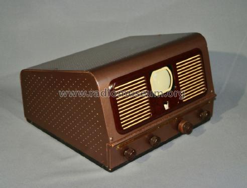
- Forma
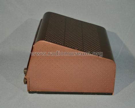
- Sobremesa apaisado (tamaño grande).
- Ancho, altura, profundidad
- 16 x 11 x 16 inch / 406 x 279 x 406 mm
- Anotaciones
-
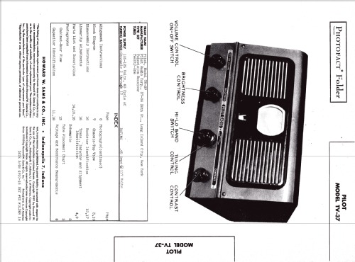
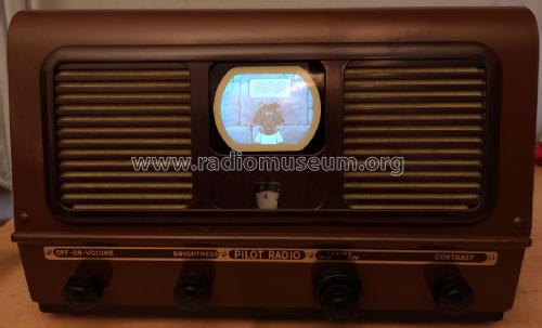
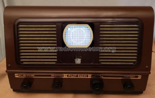
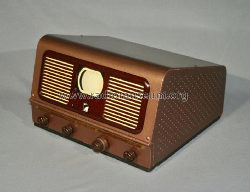
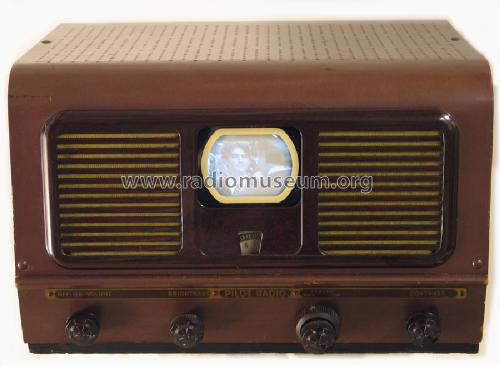
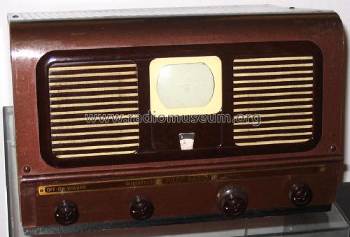
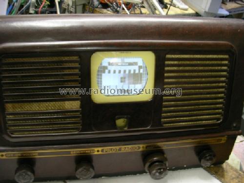
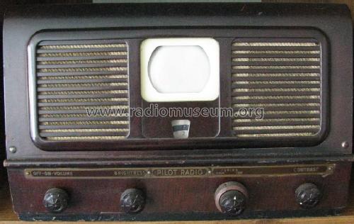
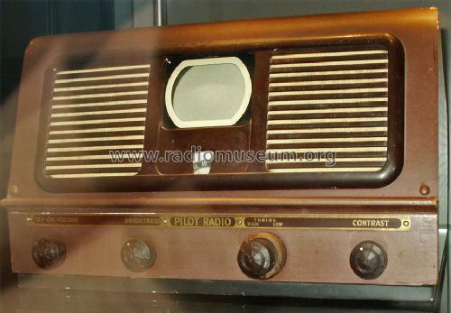
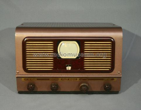
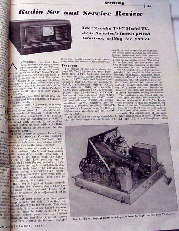
Portable US TV Set, 3" Pic. Tube from Pilot Radio Corporation. The advertising was heavily targeted to college students and the set was sold for $99.95. It has a continuous tuner and tuned channels 2 -13 in two bands. The designer was Werner F. Auerbach who explained the small screen in an IEEE-Interview as a question of costs. Two and a half years after, Motorola could compete it with a 5" screen.
According to Radio-Electronics the launch of the then cheapest so called "Low-Cost Video" as "Candid T-V" was in September 1948. The weight is less than 15 pounds and the text gives measures of 14 by 9.5 by 13.5 inches. The measures are without an alligator leatherette carrying case. The set offers full 13 channel coverage. The four principal controls are for tuning, brilliance, contrast, and volume.
- Peso neto
- 14.9 lb (14 lb 14.4 oz) / 6.765 kg
- Precio durante el primer año
- 99.00 $
- Procedencia de los datos
- -- Collector info (Sammler)
- Referencia esquema
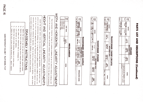
- Photofact Folder, Howard W. SAMS
- Documentación / Esquemas (1)
- SAMS set 62 folder 16; Rider TV vol. 2, page 2-1
- Documentación / Esquemas (2)
- Photofact Folder, Howard W. SAMS (Set #62 Folder 16 dated 5-49)
- Autor
- Modelo creado por un miembro de A. Ver en "Modificar Ficha" los participantes posteriores.
- Otros modelos
-
Donde encontrará 544 modelos, 271 con imágenes y 410 con esquemas.
Ir al listado general de Pilot Electric Mfg. Co. (Radio Corp.); Brooklyn (NY)
Colecciones
El modelo Pilot Candid es parte de las colecciones de los siguientes miembros.
Museos
El modelo Pilot Candid se puede ver en los siguientes museos.
Contribuciones en el Foro acerca de este modelo: Pilot Electric Mfg.: Pilot Candid TV37
Hilos: 3 | Mensajes: 4
Fellow Radiophiles:
One of the most popular B&W TV sets among American collectors is this Pilot Candid TV-37 from 1948. This was the first set to sell for less than $100(US); it was launched on the market for $99. This set was designed by the German-born US immigrant Werner F. Auerbacher at Pilot corporation. More about Mr. Auerbacher in an interview of at the IEEE Global History Network:
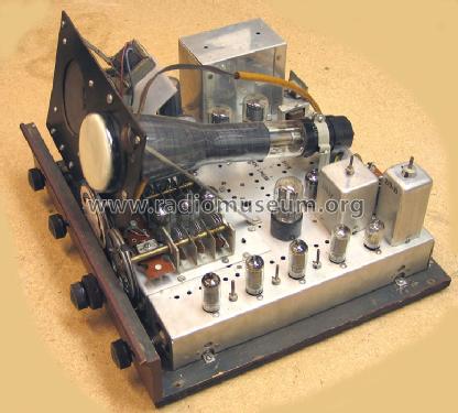
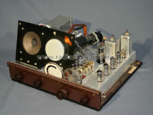
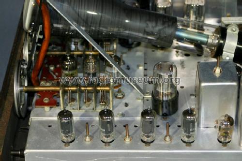
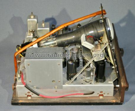
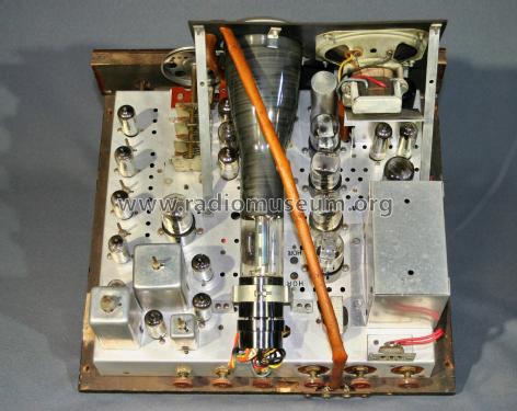
The set uses the 3KP4 B&W 3" CRT and was meant to be viewed while sitting at a table near the set. The narrow long CRT makes the chassis look more like an oscilloscope or early spectrum analyzer than any contemporary sets that had typically 7" CRT's. In fact, the green phosphor version 3KP1 was designed for oscilloscope service. This green phosphor version 3KP1 is more common than the white phosphor version and is sometimes used by collectors as a cheaper alternative to the white phosphor 3KP4.
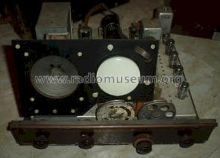
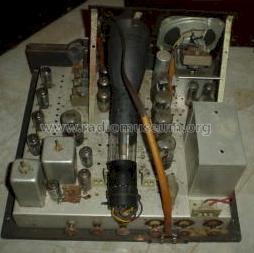
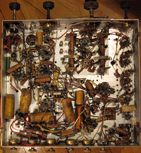
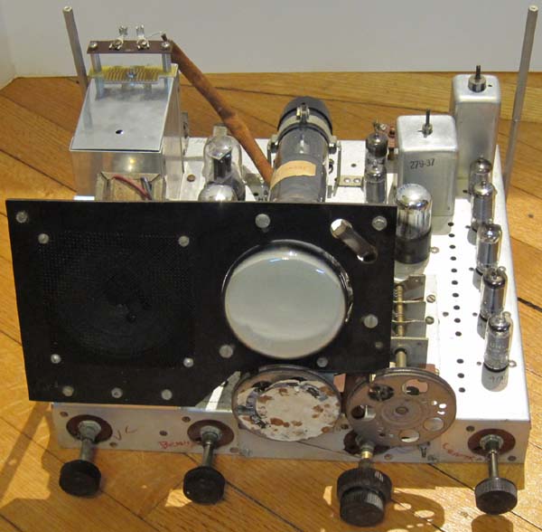
The chassis as found.
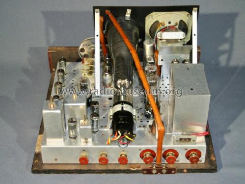
The original 3KP4 was included in this set, but it was removed for these photos. The original electrodynamic speaker failed probably during the original use. The failure was a misalignment of the voice coil that made it scrape the voice coil gap. A permanent magnet (PM) speaker was added but the original was kept because it's voice coil was also used as a filter for the +105VDC supply rail.
| The second speaker on right is not original. | CRT removed from center. | Original electrodynamic speaker with field coil. HV cage. Temporary standoffs. | Unrestored, original caps and resistors. |
 |
 |
 |
 |
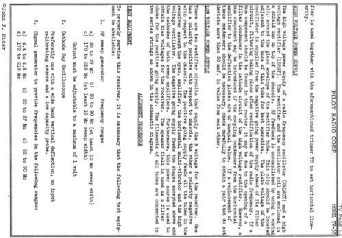
The DC power supply

|
.JPG)
|
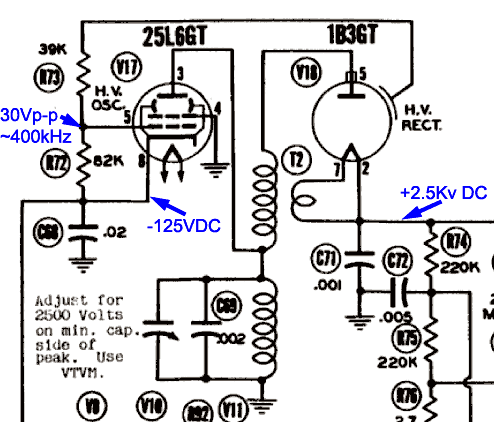
This set operates from a nominal 110V AC-only, but has no power transformer for isolation from the mains. The positive peaks of the 110VAC are rectified by a 25Z6 to create a nominal B+=105VDC and the negative peaks are rectified by a 35W4 to create a nominal B-=-125VDC. The scope photo shows the measured DC voltages. The B+ rail is very well filtered to power the small signal stages. The filter is a classic "pi" C-L-C filter that uses the speaker field coil as a ripple choke. The ripple at the B+ rectifier 25Z6 rectifier cathode with the 40uF supply filter is 11Vp-p, which gets reduced to 140mVp-p by the speaker field coil choke and output 100uF filter capacitor.
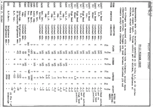
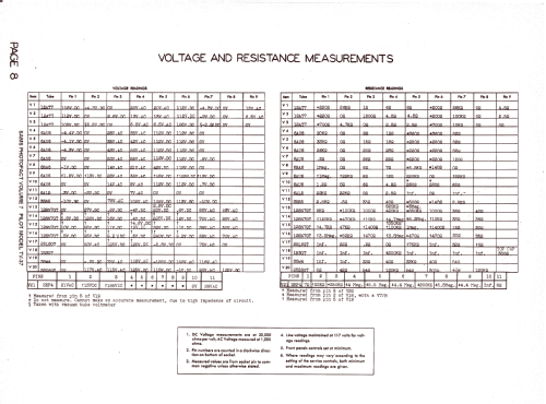
The RF, IF, Audio, Video amp stages and Vertical oscillator are powered by the positive B+ rail. The 25L6 HV oscillator and Sync Amp/DC Restorer and Horizontal oscillator are powered from the B- rail. The ripple at the B- rail is 1Vp-p. The horizontal and vertical electrostatic deflection amplifiers 12SN7x2 dual triodes operate with 230V between the B+ and B- rails to insure a linear ~150Vp-p deflection plate swing. The voltage chart in the Rider notes shows that the B+ rail may change from 95V to 105V as a function the contrast setting, which sets the anode current of the four Video IF stages.
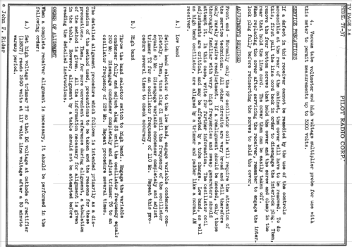
The 2.5kV second anode CRT power supply
 |
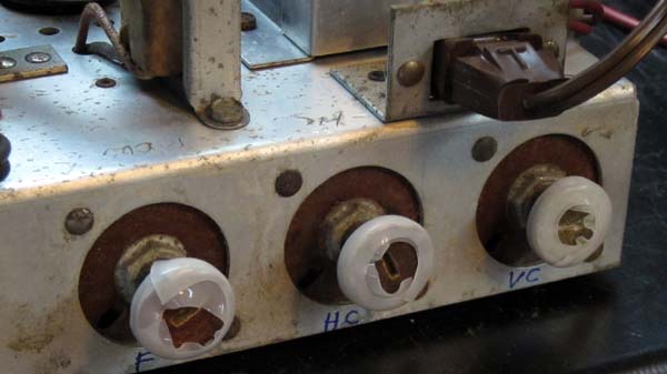 |
A note of caution: Be very careful when measuring the 2.5kV voltage. One of the classic recommendations is to keep the left hand behind your back while you hold the measurement probe with your right hand to avoid an accidential passage of current through the chest. The three controls at the rear left for Vertical centering, Horizontal centering and Focus control all have up to 2.5kV on their shafts and are mounted on phenolic board insulators. I covered these three controls in my set with high voltage insulating tape.
I replaced the 1B3GT HV rectifier with the compatible 1K3A/1J3 from my collection. The replacement of the 1B3GT High voltage rectifier requires adjustment of the feedback ring that slips over the middle section of the tube.
 |
 |
I used an RCA WV38A 20kΩ/V multimeter in the 5kV scale to measure the second anode voltage of the CRT at the 220k//5nF HV filter output that drives pin 7 of the CRT. This multimeter has 20kΩ/V*5kV=100Meg internal resistance in the 5kV scale. The voltage chart in the Rider notes indicates the second anode voltage at 2550V with the brightness control at minimum and down to 2400V with the brightness control at maximum.
The Heater String
The heater string was traced out manually because it differs substantially from the Sams Photofact schematic and from the schematic published by John F. Rider. (See the TV37 model page for Sams and Rider publication numbers). The following table shows the sequence for the two heater strings, which have the heater of the 3KP4 CRT heater in common. The blue column shows the original voltage drops at each tube, the yellow shows the specified values and the pink column on the right shows the final values after restoration.
| 120VAC 590mA | 300mAx2 | Measured with original 3R Resistors | Measured with 10R in parallel with 3R | |||||
| First heater string | HOT | 12/20/2014 | January 2, 2015 | |||||
| Tube | Function | Heater Pins | Voltage | R-drop | Specified | Heater (V) | 3//10 R (V) | |
| 3KP4 | CRT | 11,1 | 5.4 | 6.3 | 6.0 | |||
| 33 | R | 9.4 | 10.0 | 9.8 | ||||
| 35W4,35B5 | Rect B-,Audio | 4,3 | 35.1 | 35.0 | 35.8 | |||
| 25L6 | HV Osc | 7,2 | 24.7 | 25.0 | 24.4 | |||
| 3 | R | 1.2 | 0.9 | 0.9 | ||||
| 12SN7 | Hor Multi | 8,7 | 12.2 | 12.6 | 12.4 | |||
| 6AU6 | Sync, DC Rest | 4,3 | 5.9 | 6.3 | 6.1 | |||
| 6BA6 | Video | 4,3 | 5.8 | 6.3 | 6.6 | |||
| 3 | R | 1.3 | 0.9 | 0.9 | ||||
| 6AU6 | Sound IF | 3,4 | 5.5 | 6.3 | 5.6 | |||
| 3 | R | 1.0 | 0.9 | 0.8 | ||||
| 6AL5 | Ratio Det. | 4,3 | 6.3 | 6.3 | 6.5 | |||
| total | 100.9 | 12.9 | 104.1 | 12.7 | 103.4 | 12.4 | ||
| 113.8 | 116.8 | 115.8 | ||||||
| Second heater string | ||||||||
| 3KP4 | CRT | 11,1 | 5.4 | 6.3 | 6.1 | |||
| 25Z6 | Rect B+ | 2,7 | 22.6 | 25.0 | 24.4 | |||
| 12SN7 | Vert Multi | 8,7 | 11.9 | 12.6 | 12.4 | |||
| 12SN7 | Vert Amp | 8,7 | 13.0 | 12.6 | 13.2 | |||
| 12SN7 | Hor Amp | 8,7 | 11.0 | 12.6 | 11.5 | |||
| 3 | R | 2.3 | 0.9 | 0.8 | ||||
| 6AU6 | 4th IF | 4,3 | 6.0 | 6.3 | 6.4 | |||
| 3 | R | 1.3 | 0.9 | 1.0 | ||||
| 6AU6 | 3rd IF | 4,3 | 5.2 | 6.3 | 5.5 | |||
| 3 | R | 0.9 | 0.9 | 0.8 | ||||
| 6AU6 | 2nd IF | 4,3 | 5.8 | 6.3 | 6.0 | |||
| 3 | R | 1.1 | 0.9 | 0.9 | ||||
| 6AU6 | 1st IF | 4,3 | 5.5 | 6.3 | 6.7 | |||
| 3 | R | 1.3 | 0.9 | 1.0 | ||||
| 12AT7 | RF | 4-5,9 | 5.7 | 6.3 | 6.3 | |||
| 12AT7 | MIX | 4-5,9 | 6.5 | 6.3 | 6.8 | |||
| 12AT7 | OSC | 4-5,9 | 6.0 | 6.3 | 6.5 | |||
| CHASSIS | 104.6 | 6.9 | 113.2 | 4.5 | 111.8 | 4.5 | ||
| 111.5 | 117.7 | 116.3 | ||||||
Many of the 3Ω resistors in the two heater strings had increased to 4Ω-6Ω. Adding 10Ω in parallel with each of the 3Ω resistors got the average resistance back to 3Ω. This added nearly 9V back to the heaters on one string and about 3V back to the other string and increased the CRT heater voltage from 5.4V to 6V.
The 6.3V CRT heater draws 600mA and is in series with both 300mA heaters. The heater in the CRT has a lower thermal mass than the heaters in the other tubes and tends to overheat brightly for several seconds when the set is first turned on. This may cause the heater of the rare 3KP1 CRT to burn out more quickly, so an anti-series pair (anode-cathode-cathode-anode) of 8.2V 1A Zener diodes was wired in parallel with the CRT heater to shunt out most of the excess current during turn-on an limit peak voltages across the heater to 8.2V+0.7V~9V. There is still a turn-on brightening with up to 9Vrms, but it is much less pronounced than the original over-voltage. The small heaters of the 6AL5 Ratio Detector glow very brightly when the set is turned on, but this is OK because this is a cheap easily replaced tube and while it glows brightly with temporarily excessive voltage drop it protects the rest of the tubes in the heater string.
Low heater voltage for particular tubes in a heater string results in low tube performance and may affect various aspects in the set operation. For example, the 6BA6 video amplifier tube that came with this set dropped only 4V across it's heater, thus greatly reducing it's gain. Each tube heater drop was measured in the string to be sure that it was not disproportionately low. Some good tubes simply have a disproportionately lower internal resistance at lower operating current which will show a low voltage drop in the series string and should be replaced, but they will work fine when powered in shunt by a transformer in another set.
Operating the series strings at full voltage is also very important because tubes are manufactured to have a specific current draw only at the specified operating voltage (i.e. 300mA at 6.3V). If the tubes are operated at a lower series string current due to excessive external string resistance in the 3Ω resistors, some tube heater voltages will drop more than others due to the different I/V curve characteristics of the tube heaters of different types or from different manufacturers.
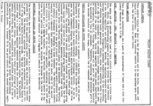
Electrostatic Deflection
 |
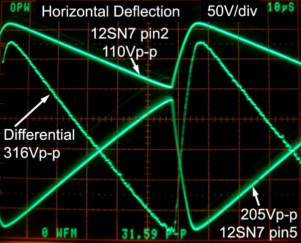 |
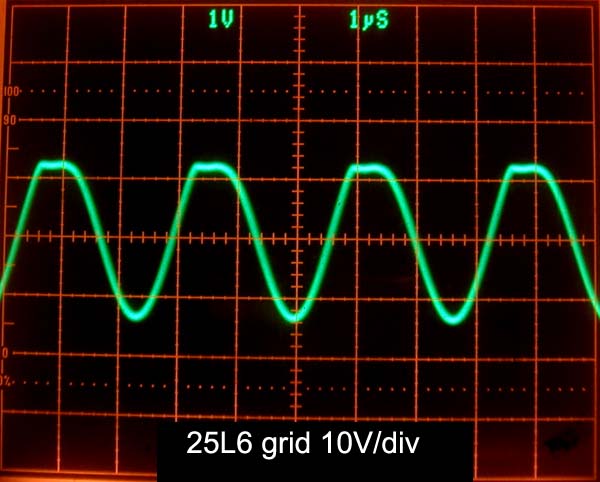
The vertical and horizontal deflection voltages are generated by two Schmidt-trigger multivibrators. Each multivibrator is comprised of a 12SN7GT dual triode. The needed linear ramps are taken from the initial voltage rise in the RC networks at the vertical and Horizontal hold control pot circuits. The Vertical and Horizontal saw-teeth at the second control grid pin 4 of the 12SN7GT multivibrators is only 10Vp-p.
Vertical and Horizontal sync signals are first stripped from the video signal by the 6AU6 Sync amplifier as described below and are then separated by simple RC filters into positive +2V vertical and -0.5V horizontal sync pulses to the 12SN7 multivibrator control grid pin1 inputs. These pulses drive the input of the Schmidt trigger Multivibrators at pin 1 of the 12SN7GT. This type of multivibrator is synchronized when the sync pulses force the end of each sawtooth ramp.
When no sync pulses are present, the sawtooth duration is longer, the deflection frequency is lower and the amplitude is higher. If the video signal is very noisy, or only video noise is present on the screen, the edges of the image become very jagged as the deflection saw-teeth are randomly reset by noise pulses. In the absence of video signal the deflection frequencies can easily decrease 30% while the amplitudes increase by the same percentage. If the free running frequency is too high, synchronization is not possible. This set locks Vertical and Horizontal deflection easily, if the overall video gain is set correctly with the contrast control. When debugging the operation of the 12SN7GT multivibrators and deflection amplifiers always be sure to have a sync signal present.
 This design is very tolerant of resistance increase over time in the carbon resistors. I found a 25% increase in most resistors in the multivibrators, but this was easily overcome with the Vertical and Horizontal hold and size controls. Carbon resistors usually go up in value over time. Increases in resistance over 30% may cause problems. Some restorers like to replace all resistors as a matter of course, but I prefer to leave in place as many original resistors as possible and I am more inclined to add a shunt resistor to correct the value of a drifted resistor.
The 180k ground return resistor at the grid of the Vertical Amplifier Pin1 had increased to 360k, thus doubling the voltage drive to this stage, which produced terrible vertical linearity. Replacing the resistor corrected 90% of the linearity problem and made the p-p amplitudes at the two opposing phase vertical deflection plates closer in amplitude. The resistor was left at it's original location with one lead clipped open and folded away. The Vertical Amp employs positive feedback with 5.6Meg from the pin 2 plate of the output triode to the pin 4 grid of the input triode. This 5.6Meg is only in the Sams schematic version. There is additional positive feedback from the pin 3 output cathode to the pin 6 input cathode. I found empirically that AC-shorting out this second positive feedback path between the cathodes with a 10uF across the 10k cathode bias resistor eliminates the last bit of vertical linearity distortion. The alignment section in the Sams and Rider documentations include instructions for the horizontal and vertical linearity adjustment.
The voltage dependency of the capacitance of the replacement 0.05uF Z5U ceramic coupling capacitors between the Vertical Amplifer and the CRT vertical deflection plates has no effect on Vertical linearity because the capacitance is large enough to keep the voltage across the caps fixed. The deflection voltage is on the order of 150Vp-p, as shown in the scope photo, and the ripple on the Vertical coupling caps is much less than this. Ceramic disk capacitors should not be used to replace any capacitors that create ramp voltages, as is found in the sawtooth generation in the Vertical and Horizontal multivibrators.
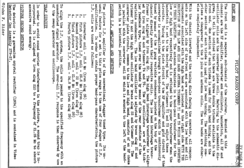
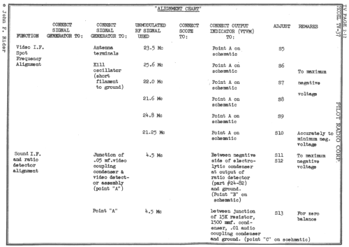
Video IF: Carrier at 25.6MHz, Sound at 21.25MHz
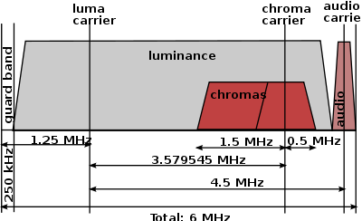 The Video IF Alignment instructions from Sams and Rider both call for the same fixed frequencies to be peaked by the same tanks in the range from 25.6MHz for the video luma carrier and 21.25MHz for the FM audio 4.5MHz sub-carrier. Note that the local oscillator operates 25.6MHz above the RF carrier. This "high side" frequency LO injection causes the relative location of the sound and video carriers to be reversed in the IF signal. For example, for analog US channel 3, the RF video luma carrier frequency at 61,25MHz is lower than the 65.75MHz audio sub-carrier by 4.5MHz. In the IF stages, the sound sub-carrier frequency is below the video carrier frequency. Note that the original analog TV transmitters send only a vistigial amount of the lower sideband just below the carrier and sent the video information and audio FM carrier on the upper side-band. A video modulator from a VCR, Digital TV tuner, or DVD player on channel-3 does not supress the lower sideband, so that it is possible to receive the signal from these modulators at two adjacent locations in the continuous tuning dial of the Pilot-TV37. Depending on the final shape of the video IF alignment, one location may tune in a little better than the other location. More on the US analog TV spectrum at Wikipedia.
Video IF Alignment
The 1N34 video detector inside the video IF output can was replaced with a new diode, while leaving the original diode clipped open in place.
 |
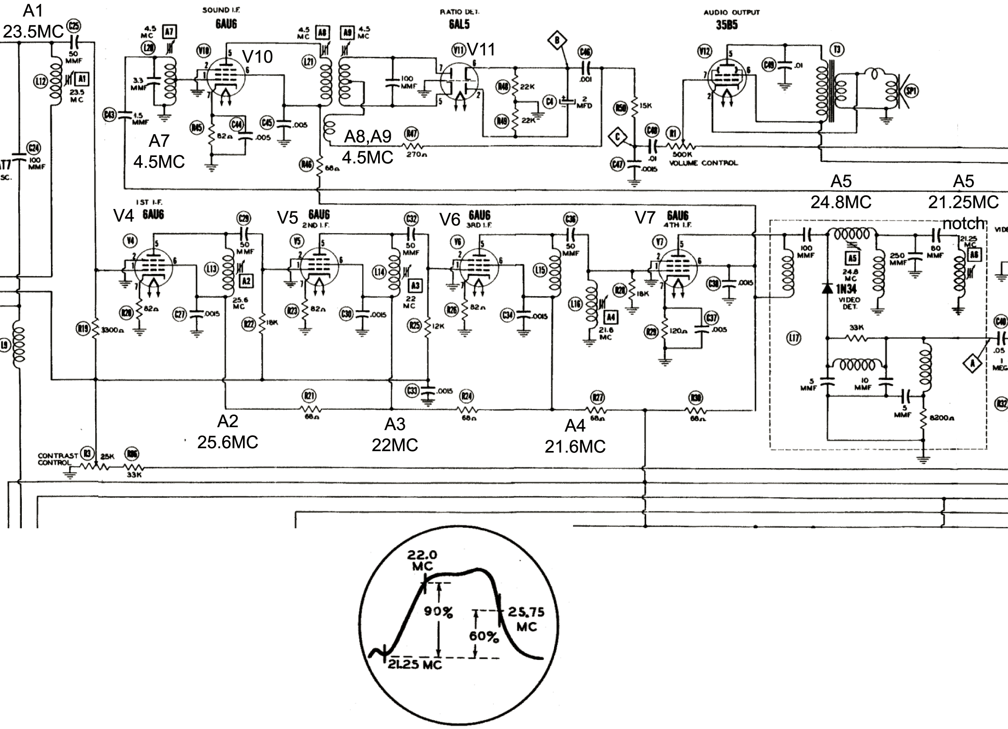 |
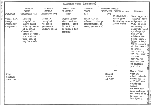
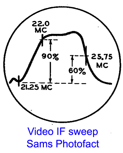
My first attempted Video IF alignment was done by injecting the recommended fixed frequencies in the Sams Photofact alignment instructions with a few turns of wire around the 12AT7 mixer tube, while the local oscillator 12AT7 tube was disabled by grounding it's heater at pins 4&5. I peaked all the Video IF tanks to each corresponding frequency, but ended up with a video IF bandwidth that was simply too narrow to tune the image and sound at the same time. The video bandwidth curve in Sams is at best 4MHz wide, thus making it impossible to tune in sound and video at the same time. I had to give up on the recommended fixed frequency alignment and spread out the alignment frequencies outward to be sure to get at least a 4.5MHz bandwidth in a sweep test. I ended up with a 5MHz bandwidth, thus making it possible to get clear sound and a clear locked picture at the same time. Before widening the bandwidth, it is a good idea to start with the fixed frequency alignment. See the schematic excerpt on the right with the resonant frequencies for each of the aligned video IF tank circuits.
It is important to watch out for oscillation in the video IF, as recommended by the Sams alignment istructions. The four 6AU6 video IF stages are not neutralized, so it is imperative that each stage be tuned to sufficiently different frequencies at it's grid and plate tanks to avoid regenerative feedback and oscillation. The stagger-tuned design if the IF strip is what makes it possible to avoid neutralization. Other contemporary sets had fewer IF stages and lower overall RF/IF gain. This set has enough RF/IF gain to produce full noise on it's screen and speaker with the IF gain set to maximum with the contrast control.
There is a sound IF notch filter as a series 21.25MHz tank inside the video detector IF can. This notch is meant to remove the 4.5MHz sound IF carrier from the detected video signal, but the 4.5MHz sound IF is picked up after this notch filter and the sound IF is thus also attenuated by this filter. I found I had to tune this notch outside the 5MHz video IF bandwidth to get sufficient sound IF carrier out and there was no evidence of 4.5MHz dot crawl on the CRT screen. The sensible thing would have been to place the 4.5MHz IF sound trap after the sound IF pickup, not before it. The location of the sound IF notch filter in the signal chain remains a small mystery.
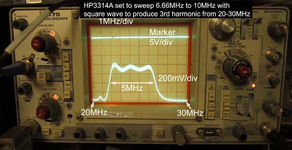 I don't own a sweep generator that sweeps from 20MHz to 30MHz, so I improvised by sweeping the square wave output of my HP3314a from 6.66MHz to 10MHz. This 50% duty cycle square wave produced sufficient output at it's third harmonic from 20MHz to 30MHz. The square wave was applied unfiltered with a few turns of wire around the 12AT7 mixer tube as described above. The photo shows about 600mV of detected video at point A in the Sams schematic, just before the 0.05uf AC coupling cap to the grid of the 6BA6 video amplifier.
4.5MHz Sound IF
The sound IF alignment works conventionally with peaking of the two 4.5MHz tanks at the grid and plate of the Ratio Detector Driver 6AU6 Pentode. The tank at the plate is the primary of the ratio detector transformer. The secondary of the ratio transformer is tuned conventionally for a null DC output from a fixed 4.5MHz input or to obtain the classic S shape if a sweep generator sweeping 4.4MHz to 4.6MHz is used.
A side note on the 4.5MHz sound sub-carrier pickup from the detected video signal: The video RF carrier must be present for the audio RF carrier to be detected and heard in this set. For example, simply feeding the 65.75MHz sound RF carrier from channel 3 without the 61.25 video carrier will not produce any detectable audio because it will not appear as a 4.5MHz subcarier in the detected video. If the sound is to be detected without a video sub-carrier, then the sound IF must be picked before video detection as a 21.25MHz IF instead of at 4.5MHz IF after the video detector. The front end of this set can tune the FM audio stations directly above channel 6 at 88MHz, but they can't be detected and heard for the reasons just cited.
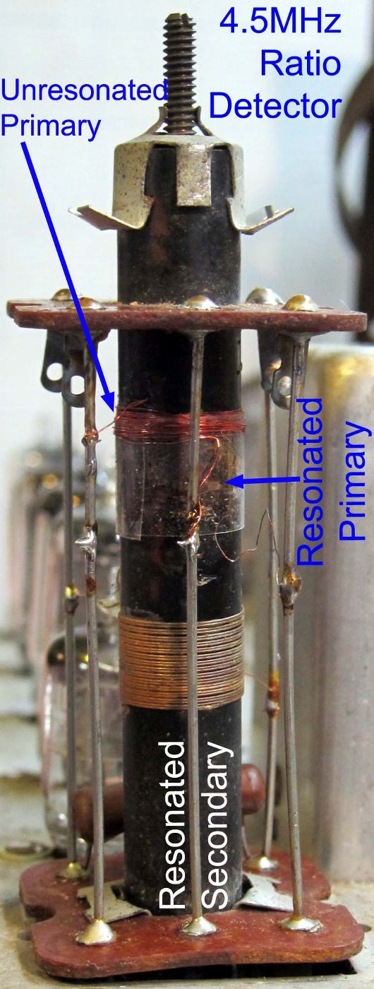
FM Ratio Detector Transformer Repair
One of the more difficult repairs was the open in the primary of the FM ratio detector transformer. It was necessary to remove the few (~10) turns of the unresonated secondary winding to repair the open spots of the primary. Only the last few turns of the single layer primary had to be rewound. Then the unresonated secondary was re-wound with new wire over the renewed section of the primary. A piece of clear plastic tape insulates the old fragile primary winding from the new unresonated secondary winding. The gain of the sound IF driver was measured around 50 with an RF detector probe improvised with a 0.01 coupling cap, a grounded 1N4148 diode and 1Meg load resistor driving a 10Meg DC voltmeter. When this probe was connected to the 4.5MHz tank circuits, the detuning effect of the probe capacitance was accounted for with the change in DC voltage across the 2uF electrolytic cap in the ratio detector. 200Vp-p of 4.5MHz at the 6AU6 plate results in 30V p-p at the secondary, which develops nearly 30VDC across the 2uF electrolytic capacitor, but the ratio detector only yields 4 volts p-p of audio out. The low sound IF audio gain and the low sensitivity of the ratio detector are explained by a relatively low measured Q=30 at the sound 4.5MHz IF tanks. The Q of the repaired winding was about the same as the Q of the other windings.
Contrast control and sound buzz
After the set was well aligned and fully operational, it became apparent that the contrast level was relatively low when the video IF gain was set for best sync stability and buzz-free audio. The contrast in this early set is not controlled after video detection as in later sets, but by changing the DC grid bias and thus the gain of the four 6AU6 video IF stages. The video contrast control also affects the audio signal gain as well as the gain of the sync pulses. Later set designs had keyed Automatic Gain Control for the video IF stage to guaranty proper sync signal levels independent of video modulation. (You will notice that the audio loudness is only affected when the contrast is greatly reduced. This occurs because the Ratio detector will tend to keep the audio output level constant for a wide range of sound IF carrier levels, say between 5Vp-p and 30Vp-p.) The contrast could be improved by lowering the brightness but this makes the already relatively dim 3KP4 early B&W CRT even dimmer. If the contrast is turned up to make the picture contrast look good, there is a buzz in the audio. The reason for the buzz is that the contrast control increases the video signal at the input of the 6BA6 Video Amplifier and this causes the 6BA6 to go into clipping at the negative tips of the sync pulses which also then clips out the 4.5MHz sound IF sub-carrier. The remote cutoff 6BA6 was probably chosen as video amplifier to help reduce this clipping, as compared to the more obvious choice of a sharp cutoff 6AU6 as the video amplifier. The solution to get more contrast without clipping the Video Amp tube was to find a tube with higher gm (transconductance) that would produce a wider video plate swing with grid drive that is small enough to avoid clipping. The gm of 6BA6 is 4.4mS. I replaced it with a 6CB6, which has gm=8mS, thus nearly doubling the Video Amp output swing without any signs of clipping at the plate or sound buzz. The 6BA6 and 6CB6 pinout differs only in that pins 2 and 7 for the cathode and suppressor grid are swapped, but both pins 7 and 2 are grounded in this set, so either tube will work in the Video Amp socket.
Sync separation and Video DC restoration

The 6AU6 stage that follows the 6BA6 video amplifier has the primary purpose of extracting the vertical and horizontal sync pulses from the video signal to synchronize the vertical and horizontal deflection.
This 6AU6 pentode also provides video DC restoration by reintroducing the correct DC level to the control grid (Wehnelt cylinder) in the CRT to set light and dark values at a fixed level. The DC restoration at the CRT grid is needed because the video signal is AC-coupled to the video amplifier and to the CRT cathode. But many contemporary American TV sets did not have DC video restoration.
This elegant scheme works as an envelope detector where the rectification current pulses become the sync signal at the 6AU6 plate and the DC restoration voltage envelope appears at the 6AU6 cathode.
The cathode with it's relatively high 22k resistance load and 5uF filter capacitor works as a cathode envelope detector and follower. When the video signal is absent, the DC drop across the 22k//5uF cathode load drops to about 4V. When the video signal amplitude increases and the sink pulses exceed 4V, the grid starts to conduct, which increases the average DC level at the grid and consequently at the cathode. The DC voltage that is developed at the cathode follows the peaks of the sync signal at the grid. When the video signal amplitude reaches 50Vp-p, the cathode voltage drop increases to 14V. A pure white scene increases the cathode drop further to about 17V.
The 6AU6 cathode voltage drives the CRT control grid directly. The sync peaks and the black level of the AC-coupled video signal at the CRT cathode vary by the same amount as the DC level variation applied to the CRT grid. The difference between the sync peaks and black level at the CRT cathode and the CRT grid remain thus constant and the DC video level is thus fully restored.
When the video signal is over-driven with with too much contrast, the sync peaks become compressed and the DC restoration stops working as the 6AU6 cathode no longer rises in response to increased Video amplitude.
The values marked in blue in the schematic excerpt were taken with a 6CB6 replacing the 6BA6 as video amplifier. The 6BA6 only provides up to 25Vp-p of video amplitude, while the 6CB6 provides twice that amplitude.
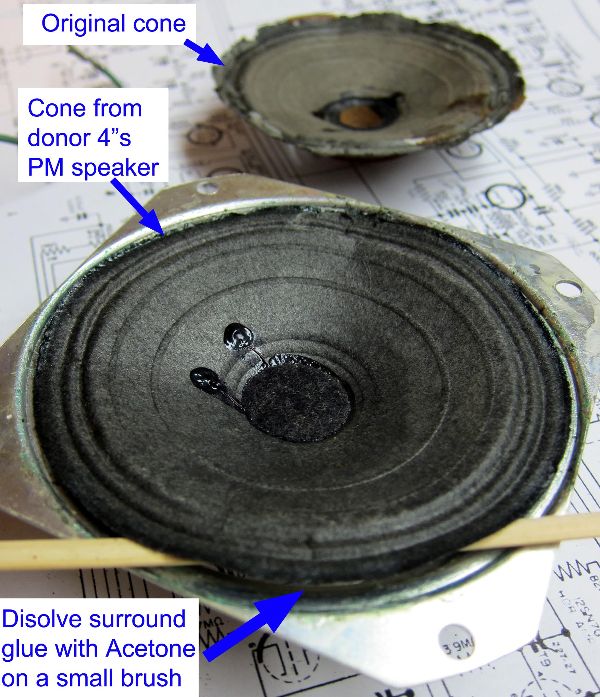
Speaker cone transplant and voice coil gap adjustment.
 |
 |
 |
 |
 |
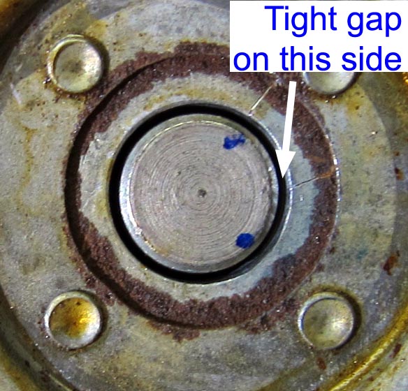
The most difficult repair in this set was the speaker restoration. The speaker had good continuity at the voice coil and field coil, but the cone was torn and the paper cylinder of the voice coil scraped against the voice coil gap. The original speaker has a US standard 4" frame and 3.5Ω voice coil, but it also has a field coil which serves as power supply choke, as explained in the DC Power Supply section above. This makes it very difficult to find a speaker replacement because most speakers have a permanent magnet and also explains how this set ended up with a PM speker for sound while retaining the original speaker as power supppy choke. I decided to repair it with a cone transplant from a good 4" Permanent Magnet 3.5Ω speaker. The 4" speaker size was standard in the USA for small tube radios.
Removing the paper cone: The voice coil wires were unsoldered first from the terminals on the speaker frame. The paper cone is attached to the frame with a glue that was easily loosened with acetone. The acetone was applied repeatedly with a small brush to the speaker surround and under the cone where the spider is attached to speaker frame. A few minutes of application of the acetone to keep it from drying out, was enough to free up the cone completely. Be sure to use pure acetone, not the kind that comes with oilly aditives to remove nail-polish.
Installing the new speaker cone: Removing the old speaker cone served to practice removing the cone without damage. The donor speaker cone came out easily with acetone as was done with the original speaker. I tested several glues that were both removable with acetone, and that bonded well to metal. I had no luck with the selection I had at home, so I bought speaker surround glue (Simply Speakers®, Speaker Repair adhesive #MI-3035) from a audio parts supplier. This glue bonds very well to paper and metal and can be removed with a solvent.
The new cone was first rotated to align the voice coil wires with the new terminal strip I installed on the old speaker frame. Before the cone is installed, glue is applied to the frame to attach the spider and to attach the surround at the cone edge. The speaker voice coil was centered to the pole piece with paper shims between the voice coil and the pole piece, as is usually done when replacing a speaker cone.
The cardboard rings that were removed from the old speaker are glued outside the speaker surround. The speaker should sit face down under pressure on a flat surface to insure that the paper cone and cardboard rings glue flat.
After the speaker was installed back in the set, I added a grille to protect it, as I plan to have the set out of the case for a long time.
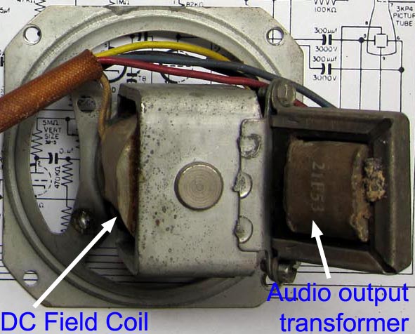
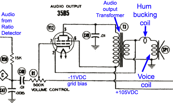 Hum bucking coil: As was customary with most speakers with a DC field coil, it also serves as DC Power Supply choke, as shown above. There was also a hum bucking coil to cancel the effect of the hum currents in the DC field coil on the reproduced sound, The hum bucking coil is tightly coupled to the DC field coil and is wired in series-opposing phase to the speaker voice coil as shown in the schematic here. The relative phase of the new voice coil and the hum bucking coil is not known at first. One way to find the correct hum bucking coil polarity is to wire it in series with the voice coil in the two possible polarities to get the lowest speaker hum. This test can be done outside the set by shorting the audio transformer primary while applying at least 20Vp-p at 60Hz to the Speaker field coil. Listen for the lowest hum on the speaker, or feel the hum with your fingers on the speaker cone. The various windings can be identified by their DC resistance: DC Field coil=146Ω, audio transformer primary= 375Ω, audio transformer secondary=0.5Ω, voice coil=2.8Ω, hum bucking coil=0.25Ω.
Paper Capacitor Replacement
 All wax paper caps greater than 5nF were renewed in place with small film or ceramic caps that were wired in series with the original cap, while shorting out the original cap with a jumper wire. The replacement capacitors are first mounted on a small perforated board as shown to wire in series with the old capacitor. The little board provides a mechanical support bridge for the original disabled capacitor and prevents mechanical stress on the disk cap.
 |
 |
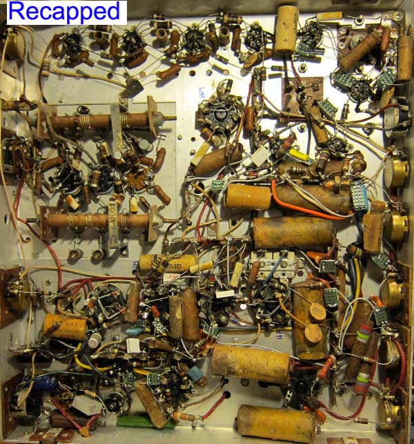 |
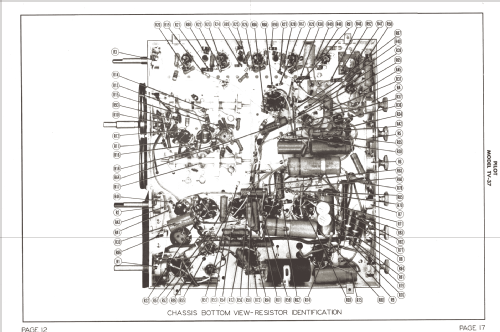
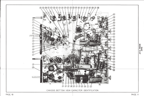
The photo shows the locations of the paper capacitors with reference designators (C##) taken from the Sams Photofact schematic, capacitance values and voltage ratings. This should be helpful in the replacement of leaky paper capacitors. Click photo to enlarge it. When a paper cap needs replacement, clip only one lead with a wire cutter, then you can test the capacitor with a leakage meter set the approximate operating or higher voltage in the circuit. If the cap needs replacement, then bend and solder the newly clipped wire ends into the little board in series with the new capacitor. Add a gray insulated in parallel with the old cap to short it out.
The detail photo shows capacitor replacements: C5 replaced with 5uF cap and C51 replaced with 0.05uF. Note the two gray wires shorting out the old capacitors.
The "Recapped" photo shows that the general appearance is similar to the original condition of the first photo. The new caps and their little boards can be found, but are not too obvious. This also helps preserve the technical history of this set. Click photos to enlarge.
The four 5nF 3kV coupling capacitors to the deflection plates were replaced with 50nF 1kV Z5U ceramic caps (Cera-Mite 565R10HKS50). These disk capacitors are only 3/4 inch in diameter and were easy to place near or under the large tubular paper caps that they replaced (photo top-right). The higher 50nF value compensates for the drop in capacitance under the 2.5kV operating bias. I tested operation of these caps at 2.5kV before using them in the set. The capacitance of Z5U capacitors is a strong function of bias voltage, with the nominal capacitance at zero bias voltage and a gradual capacitance drop toward the rated voltage. At full rated voltage, the capacitance usually drops by 80%. The voltage rating is then a range of voltages that guaranties a minimum capacitance tolerance. The breakdown voltage is much greater than the rated voltage. This is also true with related ceramic dielectrics, like the Y5V type, but not with other common ceramic types like the X5R or X7R, which change capacitance relatively little with applied bias voltage. The X7R capacitance changes less than the X5R capacitance as a function of operating voltage. The rated voltage for X5R and X7R relates more closely to the breakdown voltage.
The 0.001uF (1nF) 3kV filter cap following the 1B3GT HV rectifier was replaced with 2.2nF 3kV ceramic disk, which is less than 0.5 inches in diameter. The leads of this cap need to be positioned and soldered without sharp points to avoid corona discharge. This cap is located inside the HV housing. See the small blue disk cap in the picture of the HV supply above.
The Rider schematic notes capacitance values in the numeric form .005uF instead of 0.005uF. This can make a .005uF look like 0.05uF if the period is fade out.
Chassis and Contact Corrosion
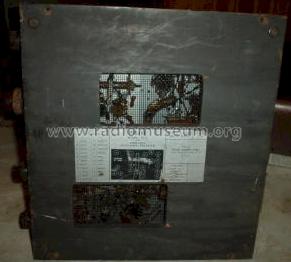
The aluminum chassis had significant corrosion on the top surface which also affected the tube sockets. I used small drops of DeOxit to clean all tube socket contacts, but even after cleaning, there were intermittent socket connections. Some of the socket holes had widened. I tested each socket hole with with a single pin that I extracted from a dead tube. I then found the loose holes, which I tightened by working a needle between the bakelite socket and the individual pin socket.
The brown corrosion on the top surface of the aluminum chassis was cleaned with the mild liquid acid in the Tarn-X silver cleaner. This was the best of several methods I tried, including polishing with abrasives and other cleaners. The Tarn-X was applied carefully with a very small soft brush that is used for art paintings. After each small section, about 2 inches square, was cleaned with Tarn-X, it was cleaned with another small brush and distilled water to eliminate the solid acid residue. Be sure to loosen the HV cage and tuner sub-chassis to clean out any Tarn-X residue that might be trapped in the seams. The chassis now looks free of corrosion, but not brand-new, with lines still present, that were left behind by the corrosion.
|
|
 |
 |
| Original chassis | Chassis cleaned with Tarn-X | Cleaned chassis detail |
Eight of the seventeen tubes had to be replaced, but the B&W CRT is very good. It seems that the previous collector may simply have stuffed this set with spare bad tubes just to have all sockets filled. Two of the tubes even had broken top tips.
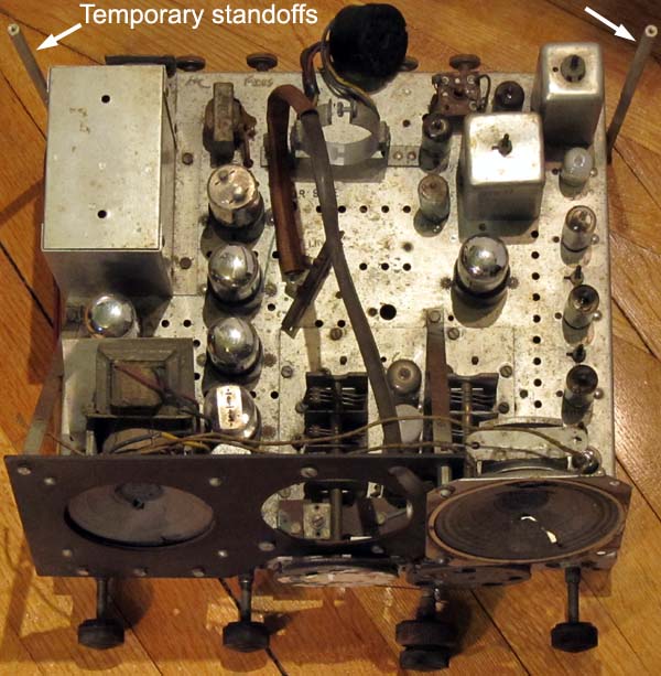
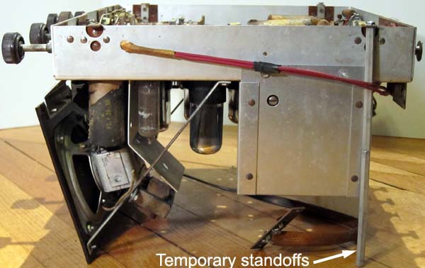
The following photo shows the chassis electrically restored. A temporary clip holds the antenna terminals in place. The two temporary standoffs are still attached to the mounting tabs on the sides of the chassis. I added a steel mesh screen in front of the speaker to avoid accidental damage during repairs. This screen is held in place by the original speaker screws.
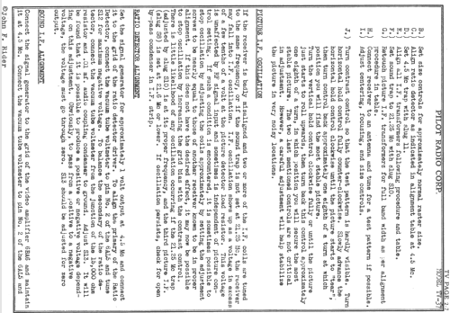
Final adjustments
The vertical and horizontal deflection amplitudes should be set such that there is some blank space above and below the picture and a little space on the left and right sides of the pictures. Increasing the deflection to cover the entire round screen will dim the image and probably introduce deflection distortion. As noted above, keep in mind that the vertical centering, horizontal centering and focus controls, that are mounted on insulators at the rear of the chassis, have up to 2.5kV on them and should be adjusted with an insulated screw driver.
After playing with this set for a while, it became clear that the two most important controls are the main tuning knob and the contrast control.The other controls usually don't have to be adjusted.
The main tuning control should be moved just short of affecting the sound quality and keep in mind that DVD/VCR/Tuner video modulator outputs can be tuned at two locations above and below the carrier. The contrast control setting is just as sensitive than the main tuning control. If set too low, the video contrast will first get reduced and with a sufficiently low contrast setting, the sound will also be reduced. If the contrast control is set too high, first there will be a sound buzz from the onset of clipping of the 6BA6 (or 6CB6 upgrade) video amp and the Video DC restoration stops working, thus making the black levels scene dependent. Then the image content starts to affect synchronization and parts of the image will be distorted. Lastly, with the most excessive contrast setting, the video IF stages will start to saturate and image contrast and sound are actually reduced.
I have found that the best contrast setting is reached just short of full black level saturation when the brightness contrast is set at maximum. Then the brightness contrast can be dropped from maximum just a little bit to get fully saturated blacks with minimal effect on the highlights.
When properly repaired and adjusted, this set gives a very nice crisp image without distortion. Once well adjusted, there is no need for further adjustment as the DC Video restoration keeps the black levels pretty constant. Click to magnify the following images.
 |
 |
 |
 |
 |
Regards,
-Joe
Joe Sousa, 14.Feb.15
Fellow Radiophiles,
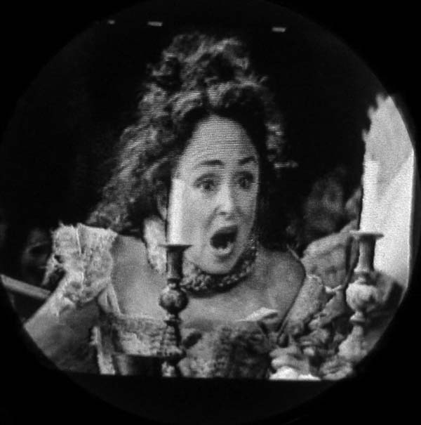
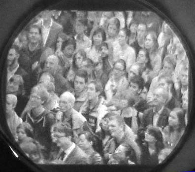
DC-restoration of the video signal is the process that fixes the black level seen in the CRT (Cathode Ray Tube), independent of scene content. For example, when watching ice skating, the scene is mostly white on the ice, but is much darker if the background changes to the audience. The exposure of the skater in the scene does not vary in transmission, but in a set without DC-Restoration, which is to say, the video signal is AC-coupled on its way to the CRT, it will have very different exposure levels on the skater, depending on light vs dark surroundings.
Click any graphs or images to enlarge them in a separate window.
LTspice Simulation with Approximated NTSC Signal
 I made a reasonable approximation of an NTSC video signal for the purposes of simulating the DC-restoration of an AC-Coupled video signal in LTspice. The graph on the right is zoomed in around the vertical sync pulse. I did not include the 3.58MHz color burst signal or the black level just before and just after the horizontal and vertical pulses. These black level sections blank the CRT beam while it returns from vertical and horizontal sweeps.
If you are closely familiar with the NTSC signal, you will see that I also did not include the extra equalization horizontal sync pulses before, during and after the vertical sync pulse.
The important thing is to get the correct duty cycle for the vertical and horizontal pulses. The horizontal and vertical sync pulses are active high only 7.8% and 1.2% respectively, which makes a net 9.0% sync duty cycle.
The amplitude of the signal was scaled to 20Vp-p of video and 6Vp-p for the sync pulses. These amplitudes are typical for the video signal at the the output of the 6BA6 video amplifier in the Pilot TV-37, which drives the cathode of the CRT through an AC-coupling cap. See the circuit excerpt below.
Nearly Perfect DC-Restoration
 With DC restoration, peak white and peak black levels stay fixed, regardless of scene content. This is typically accomplished by detecting the peaks of the sync pulses to clamp them at a fixed level.
Clamping is a peak detection process that involves storage and pushes an AC-Signal to one side of a fixed DC voltage. There is no loss of AC information.
Clipping simply clips a waveform above or below a certain level.
The simplest circuit for this is perhaps a simple diode with a grounded cathode and an input AC-Coupling capacitor driving a resistive load in parallel with the diode. The DC-restored video is at the "Video_Dio_Restore" terminal. This simple circuit compares the input "VIDEO" signal to AC-Coupled video at "Video_AC" and to a DC-restored video at "Video_Dio_Restore". The "Video_ACEnvelope" terminal also follows the positive envelope of the AC-coupled video.
The following plot shows 1.2s of video, where the scene starts out black for 0.2s, then goes white for 0.5s and returns to black for the remaining 0.5s.
The solid black lines are the zero reference levels for the three traces.
The red trace is the input video signal with +6V sync pulses and -20V peak white video.
The magenta trace is the AC-Coupled version of the input video. Note how the AC-coupled white level first steps negative at 0.2s by -20V, but then drifts to only -5V, making the white scene much darker. When the input video level steps back up to black by +20V at 0.7s, it takes about 0.3s for the proper black level to be reached. This illustrates a scene variation from white ice to a black background.
The cyan trace shows the video signal after DC-restoration at the "Video_Dio_Restore" terminal with the simple R-C-Diode clamping circuit. The cyan trace is nearly identical to the red trace. This is close to ideal DC-restoration.
 This circuit has a finite level of efficiency. One issue is 0.7V of voltage drop for a Silicon diode, but that can be overcome with a simple offset (brightness) correction. The input AC coupling cap gets charged by the positive sync peaks, and must loose very little charge between sync pulses. It is imperative that the AC-coupling cap charges much faster through the diode and source impedance than it discharges through the load resistor. Something like a 100/1 charge to discharge current ratio would be acceptable. If the load resistor is 1MΩ, then the source impedance and diode impedance would have to be less than 10kΩ if the sync pulses had a 50% duty cycle. The actual charge/discharge behavior is calculated below by taking the actual 9% V&H sync pulse duty cycle into account.
After the charge/discharge current ratio is satisfied, the time constant of the load resistor and cap also has to be long enough so that less than 1% of the charge is lost between horizontal and vertical sync pulses.
DC-Restoration in the Pilot TV-37
Early post-war B&W TVs often had no DC-restoration, or had very incomplete DC-restoration, as is the case with The Pilot TV-37 from 1949.

I have been looking into the DC restoration circuit in the Pilot TV37, as shown in the schematic excerpt. The video path from the 6BA6 video amp plate to the CRT-cathode is AC-coupled with a 0.25uF cap. The DC restoration voltage is fed into the CRT-grid by the cathode of the 6AU6 DC-restorer and sync amp.
This pentode also delivers amplified sync at its plate. This is a clever dual use of a single pentode. During the positive-going AC-coupled sync pulses at the grid, the plate turns on hard and causes the plate to swing hard negative below ground by 60V. Keep in mind that the 6AU6 operates between ground and Bminus=-99V. During this period, most of the 5mA peak cathode current actually flows to the screen grid g2 because the plate current is limited by the 220kΩ load resistor to 100V/220kΩ=450uA.
During a sync pulse, the 6AU6 pentode works as a triode follower with μ=35 with the screen grid g2 serving as the plate and the cathode follows the positive peaks of the grid voltage to keep the 5uF load capacitor charged up with the positive envelope of the AC-coupled video signal. With 85V between the cathode the screen g2 and μ=35, the 6AU6 cuts off with just -95V/35=2.4V. This limits the minimum required sync amplitude at the 6AU6 grid to at least 2.5Vp-p for reliable sync operation.
After the positive sync peaks, the 6AU6 grid goes hard negative by at least the -6V of the sync pulse for black video and by -26V for white video. The cathode also turns off like a diode, so that the charge is retained by the 5uF reservoir capacitor as the positive envelope of the video.
The CRT beam current and thus brightness, responds to the voltage difference between its grid (Wehnelt cylinder) and cathode. So the final step of the DC restoration occurs inside the CRT as the positive DC envelope of the AC-coupled video is fed to the CRT grid voltage to replace the missing DC component in the AC-coupled cathode.
The large 5uF value and the 22kΩ cathode load resistor have a 110ms time constant while the 6AU6 is cut off. The V and H sync pulses have a total 9% duty cycle with respect to the video content. The peak charging current during a white scene is 5mA and the discharge current is 0.5mA through the 22kΩ load resistor.
The charge path for the 5uF reservoir cap is through the internal 6AU6 cathode resistance and the external series 270Ω resistor. The total cathode charging resistance in simulation is 1450Ω.
Original DC-restoration Clamp Efficiency Limited to 31%
The charging time constant including the 270Ω cathode resistor is 7.25ms. This means that only 18.7% of the charge into the 5uF cap is accumulated during the 9% sync duration in the 1/60s field period. This time is 1/60*9%=1.5ms during the active H+V sync pulses in one 1/60s field sweep.
The discharging time constant through the 22kΩ load is 110ms. This means that some 12.9% of the charge accumulated on the 5uF cap is lost during the 1/60*91%=15ms between H&V sync pulses in one 1/60s field sweep.
During the 110ms discharge time constant, the capacitor voltage charge/discharge stabilizes to a constant value over several 1/60s field sweeps.
The net efficiency of the DC restoration is 100%-12.9%/18.7%=31.1%. This calculation is strongly dependent on how well modeled the 6AU6 cathode resistance is. This resistance is non-linear and depends on the cathode current. The cathode resistance in the linear calculations below is the value that makes the calculated DC-Recovery efficiency match the simulated circuit result.
 With only 31% of DC recovery, there is still a very noticeable change in the brightness level of a particular item in the scene as the background changes from dark to light.
DC-Restoration improved to 100%
The efficiency can be improved by either reducing the charging time constant or increasing the discharging time constant. The charging time constant is limited by the internal 6AU6 cathode resistance, so it can't be improved. I doubled the discharge time constant by doubling the 22kΩ load resistor to 44kΩ. Repeating the calculation, we get 64% of DC recovery. Much better, but still not 100%. One possible reason for the original 22kΩ value choice may have been to guaranty full plate saturation at the 6AU6 for a reliable full sync swing at the plate. But, I found no sync swing degradation with the 44kΩ cathode load.
DC recovery circuits are typically done in the same path that delivers the video signal to the CRT. In the Pilot TV-37, the AC-coupled video drives the CRT-cathode and the video DC-recovery voltage is fed to the CRT-grid. This means that if I were to add a modest DC recovery circuit to the CRT-cathode circuit, I might be able to make up the missing 36% of the DC-recovery voltage.
I added a 1N34 diode to the CRT-cathode circuit, like the diode type in the existing video detector shown in the schematic above, in parallel with the 180kΩ resistor passing the DC brightness bias current to the CRT-cathode. This diode was able to accumulate enough DC recovered voltage on the increased 1.25uF cathode AC-coupling cap in the video path to the CRT-cathode, that I was able to obtain close to 100% net DC restoration, with 64% DC recovered in the CRT-grid path and 36% DC-recovered in the CRT-cathode path.
I also increased the AC-coupling cap into the CRT cathode from 0.25uF to 1.25uF. The cathode charge accumulation cap was also cut in half from 5uF to 2.5uF. This improves the time constant match between the CRT-cathode and CRT-grid paths. This makes for a faster and cleaner response to scene brightness changes, as the CRT-grid should always track the black level in the CRT-cathode video.
 Having the two separate paths available for AC-video and DC-restoration is what made it possible to improve the DC restoration to 100% with such a simple fix.
Simulated DC-Restoration
This LTspice schematic was used to simulate DC restoration. The ideal sources and circuit elements on the lower left generate an approximation of the NTSC video signal with a 0.5s white scene followed by a 0.5s black scene. The 6AU6 shown was modelled in KorenTube.lib and simulates the Sync Amp and DC restoration stage of the TV37.
 These plots show the simulated DC-restoration results comparing the ideal case on the left, the original circuit in the midddle and the modified improved circuit, including the 1N34, on the right.


The first plot on the left shows results using the simple R-C-Diode circuit shown above. Ideally, the thin blue trace with the recovered DC level should match the shape of the top side envelope of the magenta AC-coupled video waveform. In this the case, the DC-recovered level is nearly ideal in the cyan trace, because it looks almost exactly like the original input video in the red trace.
The plot in the middle is a simulation of the original circuit and it is clear that the amplitude of the thin blue trace with the recovered DC level has a much lower amplitude than the top side envelope of the magenta AC-coupled video trace. The cyan trace is the difference between the blue and magenta traces. Ideally, it would have the same shape as the red input video trace. In this case The black level on the right end of the wave did move up 31% off where it should have been to match the red trace. The peak-peak swing of the blue trace is simply too small at 31% for a full DC restoration.
There is also a time constant mismatch between the magenta and blue traces in the middle plot. This makes the cyan trace lumpy. It overshoots quickly following the fast AC-coupled video, then it is brought down slowly by the undersized DC-recovered level.
The plot on the right is the simulation after I incorporated my DC-recovery improvement in the CRT-grid circuit and the additional 1N34 diode in the CRT-Cathode circuit for a net 100% recovery. There is also a change in the CRT-Cathode and CRT-Grid time constants to make them match more closely. This time constant match results in clean transitions between dark and light scenes in the final DC-restored video inside the CRT.
The magenta AC-coupled CRT trace on the right plot already shows 32% DC-recovery from the new 1N34 diode in the cathode circuit, as compared to the magenta curves on the two plots to the left, that are purely AC-coupled. Now the thin blue trace with the improved, but incomplete DC-recovery into the CRT-grid, is combined in the CRT with the partially DC-recovered magenta trace at the CRT-cathode to achieve 100% DC-recovery in the cyan trace.
Simulated Ideal vs. Original vs. Improved DC Restoration
The following plot simulates a direct comparison of ideal 100% DC-recovery in the thin black line overlaying the magenta trace, the original 31% DC-recovery in the thin black trace overlaying the AC-coupled video in the red trace and and the improved 68% DC-recovery in the thin black grace overlaying the 32% partially DC-recovered video in the cyan trance.

Measured results
The following measured results, for the improved 100%DC-restoration, confirm the simulation results.
The following scope photos show the video sisgnal for horizontal line number 24 at the CRT-Cathode and the DC-restored level at the CRT-Grid. The HP54601b oscilloscope has a TV sync mode where you can select the line number to view. The CRT-Cathode waveforms float up and down with the scene brightness, because they are AC-coupled. The CRT-Grid is supplied with the recovered DC level that follows the black level at the top of the CRT-Cathode video waveform.
The black level in the video in the first photo matches the DC grid voltage perfectly. This is the ideal case. In the the following three photos, the black level of the video on both sides of the horizontal sync pulses still match the DC level fed to the grid quite well.
The brightness of the CRT is set by the difference between its cathode and grid. The difference between the grid and cathode waveforms at the black level on either side of the H-sync pulses is zero or nearly zero in all 4 photos. This means that the DC-Restoration is very close to 100%.
You will notice that the amplitude of the sync pulses is suppressed from about 8Vp-p with a black scene down to 6Vp-p with a white image. This is due to the loading of the additional 1N34 diode I wired into the CRT-Cathode circuit to partially restored the video in the CRT-cathode path.


NTSC Test Pattern Generation
A side comment on test pattern generation: Instead of buying a classic NTSC generator, I simply used a small cheap set-top DVR with an NTSC CH3 output. I put all the test patterns that are are freely available on the web in a USB stick plugged into the DVR. You can even view the classic American test pattern, the Indian head. The DVR also works as an ATSC to NTSC converter for antenna reception off the air in the USA.
For a full report on the earlier restoration and analysis of this set go to Pilot TV37 Repair and Operational Details.
Conclusion
The possibility of injecting incomplete DC-restoration in two parallel video paths to the CRT-grid and CRT-cathode is what made it possible to reach a net 100% DC-restoration without an optimized dedicated DC-restoration circuit.
With DC-restoration improved from 31% to 100%, the TV-37 is much more enjoyable to watch with correct brightness for any scene, regardless of scene content.
Regards,
-Joe
Anexos
Joe Sousa, 26.Aug.24
Fellow Radiophiles:
The following news clip from the Early Television web site shows the market introduction of the Pilot TV37 in September 1948. Note that the version described has an aluminum cabinet and three "rectifiers". The versions that were eventually sold to the public had a wooden case and only two power rectifiers.

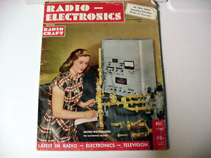
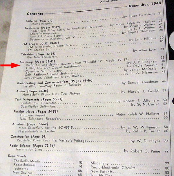
A copy of Radio Electronics December 1948 has also appeared in an on-line auction. This issue includes an article introducing the Pilot TV37.
 |
 |
 |
 |
 |
 |
Regards,
-Joe
Joe Sousa, 13.May.15