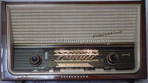
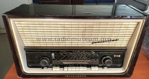
Concertino 2194 poliert
Telefunken Deutschland (TFK), (Gesellschaft für drahtlose Telegraphie Telefunken mbH
- Country
- Germany
- Manufacturer / Brand
- Telefunken Deutschland (TFK), (Gesellschaft für drahtlose Telegraphie Telefunken mbH
- Year
- 1960–1962
- Category
- Broadcast Receiver - or past WW2 Tuner
- Radiomuseum.org ID
- 23866

Koenig


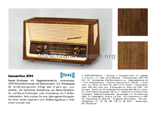


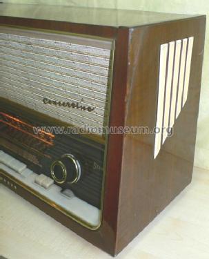

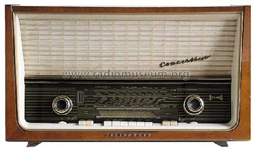


Telefunken Concertino 2194

Telefunken Concertino 2194 RW


Click on the schematic thumbnail to request the schematic as a free document.
- Number of Tubes
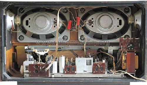
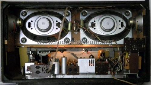
- 9
- Number of Transistors
- Main principle
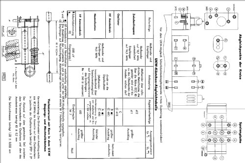
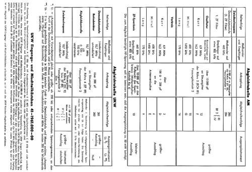
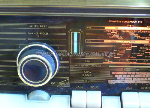
- Superheterodyne (common); ZF/IF 460/10700 kHz
- Tuned circuits
- 6 AM circuit(s) 12 FM circuit(s)
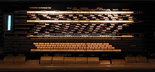
- Wave bands
- Broadcast, Long Wave, Short Wave plus FM or UHF.
- Power type and voltage
- Alternating Current supply (AC) / 110, 125, 220, 240 Volt
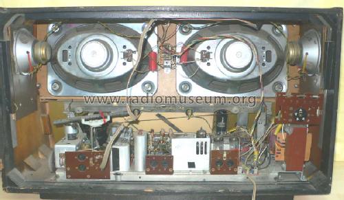
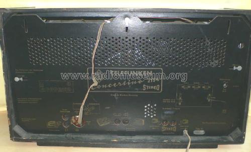
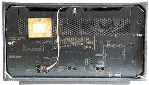
- Loudspeaker
- 4 Loudspeakers
- Material
- Wooden case
- from Radiomuseum.org
- Model: Concertino 2194 [poliert] - Telefunken Deutschland TFK,
- Shape
- Tablemodel with Push Buttons.
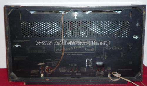
- Dimensions (WHD)
- 640 x 375 x 270 mm / 25.2 x 14.8 x 10.6 inch
- Notes
-
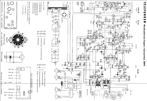
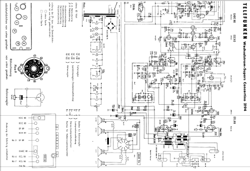
Stereo-NF-Verstärker, 7-W-Gegentakt-Endstufe in Zweiwegtechnik.
AFC wird aktiv beim Loslassen des Abstimmknopfes.Parallelgerät zum AEG Tambour 61.
- Net weight (2.2 lb = 1 kg)
- 14.3 kg / 31 lb 8 oz (31.498 lb)
- Price in first year of sale
- 459.00 DM
- External source of data
- Erb
- Source of data
- HdB d.Rdf-& Ferns-GrH 1961/62
- Literature/Schematics (1)
- -- Original-techn. papers.
- Other Models
-
Here you find 3580 models, 3167 with images and 2126 with schematics for wireless sets etc. In French: TSF for Télégraphie sans fil.
All listed radios etc. from Telefunken Deutschland (TFK), (Gesellschaft für drahtlose Telegraphie Telefunken mbH
Collections
The model Concertino is part of the collections of the following members.
Museums
The model Concertino can be seen in the following museums.
Forum contributions about this model: Telefunken: Concertino 2194
Threads: 3 | Posts: 24
Hello,
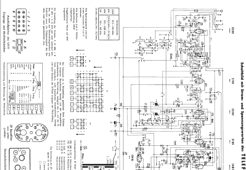
I have just overhauled a 1961 Telefunken Concertino 2194 and I have a question about its AM IF frequency. It's currently set to around 480kHz, some way off the 460kHz stated in the service manual but I don't think the set has been tampered with. Stamped on one of the IF transformers is '485kHz', which may suggest that for the UK and other export markets it was changed. Is it likely that the AM IF frequency on exported versions of this set would be set to 485kHz? I have overhauled several German built radios of this era and the AM IF frequency has always been the same as the German market sets.
If so I shall align it to 485kHz as it has drifted and the set is lacking a little gain on all AM bands.
Regards ............ Howard
Surrey Hills, England
Howard Craven, 04.Feb.14
This model has a stereo audio circuit. From studying the schematic, it seems to have an extra triode in the left channel. After the volume control, the audio signal for each channel goes through through a triode. In the case of the left channel, that triode is part of the EABC80 and in the case of the right channel the triode is part of the ECL86. The output of the right channel triode goes directly to the pentode section of the ECL86. The left channel, however, goes through the triode section of the ECL86 before it is applied to the pentode section.
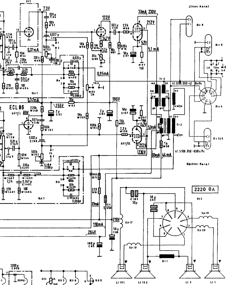
I have two questions concerning this model.
- Why the extra stage in the left channel?
- How to adjust W66, the 20k trim potentiometer in the cathode circuit of the second triode of the left channel?
Best Regards, Jim
Improved because the circuit diagram was too large.
James MacWilliams, 12.Apr.10
I am restoring a Telefunken Concertino 2194. I have replaced all the paper capacitors and a couple of resistors that were out of tolerance. The radio works well on all the AM bands - LW, MW, and KW -- and sounds great. FM (or UKW), however, is not working. It does receive one station, extremely weak, volume has to be at maximum to hear it. This station is just outside the FM band the radio should receive -- 101.0 MHz.
All the voltages are okay. I have checked the waveband keyboard switches and they are okay. I have tried known good tubes (valves) -- ECC85, EF89 (2x), ECH81, and EABC80 with no change.
I have made some DC resistance checks through the FM front end section with the ECC85 removed to verify the resistors. They are okay with the exception of W604 which should be 33k and I measure 21k. But I am not sure how to open the front end section, so nothing has been changed (or cleaned for that matter).
I am hoping for some suggestions on where to procede. Or perhaps notes on how to open and service the FM front end. Has anyone had similar problems with this model? Any guidance would be appreciated. Regards, Jim
James MacWilliams, 07.Jul.09