- Pays
- Etats-Unis
- Fabricant / Marque
- W-K (W.K.) Electric Co. (Winther-Kenosha); Kenosha, WI
- Année
- 1925
- Catégorie
- Radio - ou tuner d'après la guerre 1939-45
- Radiomuseum.org ID
- 225109
-
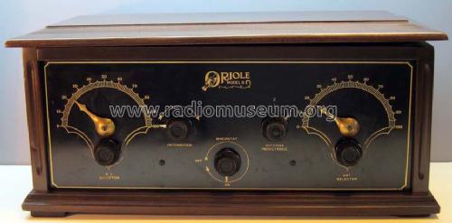
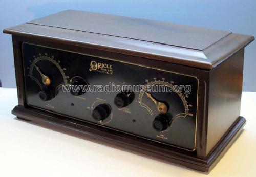
- Brand: Oriole
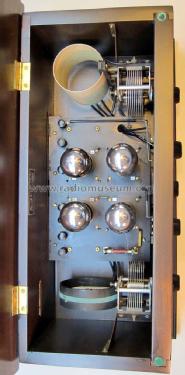
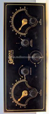
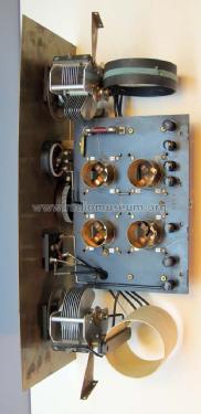
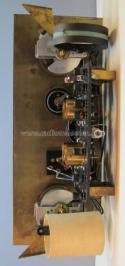
W.K.ELECTRIC CO. ORIOLE 8 SPECIAL
W.K.ELECTRIC CO. ORIOLE 8 SPECIAL 'LOGO'


W.K.ELECTRIC CO. ORIOLE 8 SPECIAL 'TUBES'
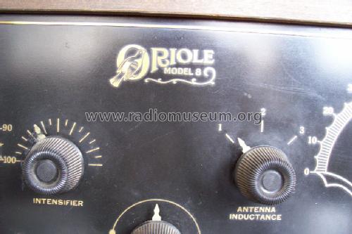
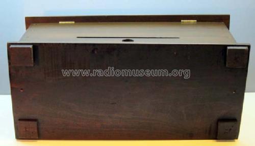
Lid warped over time on the left.

Cliquez sur la vignette du schéma pour le demander en tant que document gratuit.
- No. de tubes
- 4
- Principe général
- Récepteur TRF - par réaction (régénératif); Procédé spécial de réception. Qui peut donner des détails.
- Circuits accordés
- 2 Circuits MA (AM)
- Gammes d'ondes
- PO uniquement
- Tension / type courant
- Piles (rechargeables ou/et sèches) / 5 & 45 & 90 Volt
- Haut-parleur
- - Ce modèle nécessite des HP externes
- Puissance de sortie
- 0.1 W (0.16 W max.)
- Matière
- Boitier en bois
- De Radiomuseum.org
- Modèle: Oriole 8 - W-K W.K. Electric Co. Winther-
- Forme
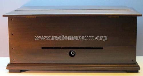
- Modèle de table boitier avec vouvercle
- Dimensions (LHP)
- 20.25 x 9.25 x 9.25 inch / 514 x 235 x 235 mm
- Remarques
-
RF stage uses cathode follower with step-up transformer to achieve a net voltage gain of 3 from the grid of the RF stage to the grid of the next stage, which is the grid leak detector. This measured voltage gain is with the "Intensifier" regeneration control turned counter-clockwise for zero regeneration. The "Intensifier" control provides regeneration from the plate of the detector stage to the grid of the RF stage. The cathode follower RF stage never oscillates on it's own, however, the "Intensifier" control can be advanced far enough when no antenna or a high impedance antenna is connected, to cause simultaneous oscillations in the RF and Detector stages.
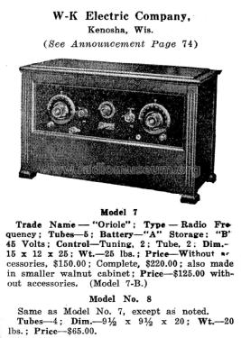
A similarly named model, the Oriole 8 Special, is listed in the Radio Collector's Guide 1921 as a 5 tube set.
- Poids net
- 15 lb (15 lb 0 oz) / 6.810 kg
- Auteur
- Modèle crée par Joe Sousa. Voir les propositions de modification pour les contributeurs supplémentaires.
- D'autres Modèles
-
Vous pourrez trouver sous ce lien 23 modèles d'appareils, 12 avec des images et 4 avec des schémas.
Tous les appareils de W-K (W.K.) Electric Co. (Winther-Kenosha); Kenosha, WI
Collections
Le modèle Oriole 8 fait partie des collections des membres suivants.
Contributions du forum pour ce modèle: W-K W.K. Electric Co: Oriole 8
Discussions: 1 | Publications: 1
Fellow Radiophiles:
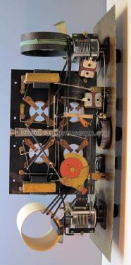
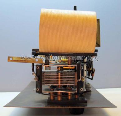
After a long search for radios with cathode follower RF amplifiers, I managed to obtain the Winther-Kenosha Oriole 8, which is part of the earliest known line of commercial radio models to use the cathode follower topology for oscillation-free RF amplification without neutralization. The cathode follower provides power and current gain, while the cathode step-up transformer and tuned circuit provide the necessary voltage gain for the grid of the next stage.
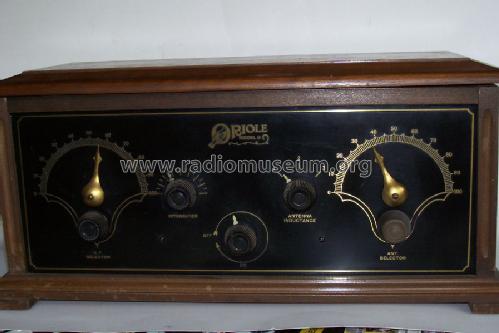
The wooden case of the Oriole was professionally restored by a cabinet maker to repair broken panels, reduce case warping and apply a new finish that was similar to the original.
In order to gain an appreciation of the merits of the cathode follower RF amplifier topology, I made two series of similar RF gain and bandwidth measurements on the Oriole 8 and on a Fada 160A Reflex TRF three-dialer. Both sets use only four 01A triodes.
The Cathode Follower RF amplifier
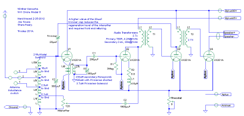
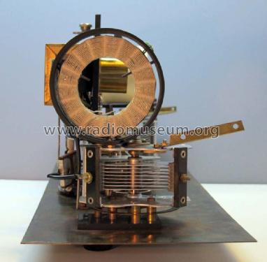
As shown in the original patent drawings for the Winther-Kenosha cathode follower, and in the next schematic of the Oriole 8 at 01A triode U1, the cathode is loaded with a bifilar winding that passes DC to power the filament, while the tight 4-turn bifilar 3.7uH winding appears as a single RF load at the cathode. The impedance seen by the cathode is increased above that presented by the 3.7uH inductance with the secondary resonance. The schematic details various measured coil characteristics, including inductance, turns ratios, Q-factor and RF impedances. I used the old uuF capacitance notation to denote pF in this schematic. (click to enlarge schematics)
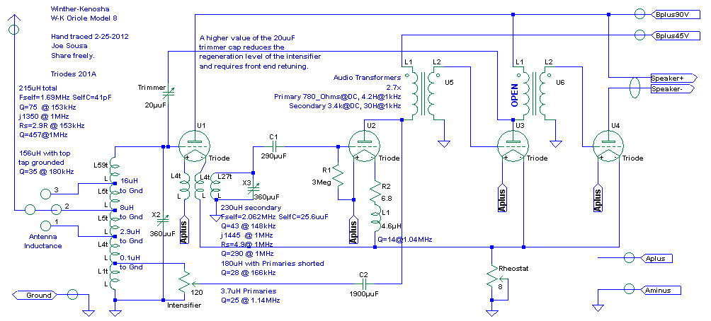
In the Oriole, the net RF gain from the grid of the cathode follower U1 to the Grid of the detector U2 was only 3 because of heavy cathode loading under the resonated 3.7uH load, which lowered grid-cathode gain to 0.2x. The tuned step-up transformer secondary with 320uH increased voltage another 15x for a net stage voltage gain of 3 from the RF cathode follower grid to the detector grid.
![]() I experimented with doubling the number of primary turns from 4 to 8 to increase the impedance and this increased grid-cathode gain to 0.4x, but the stepped up voltage at the secondary increased only 25% for a total RF gain around 4. The bandwidth also widened from 9kHz to 12kHz with these extra turns. This bandwidth was measured at the detector grid by wobbling a 1MHz CW carrier. The "Intensifier" regeneration control was set to zero. See the figure for the experimental 4 turn bifilar enameled wire coil that was wired in series with the existing 4 turn green cloth wire bifilar cathode load coil.
I experimented with doubling the number of primary turns from 4 to 8 to increase the impedance and this increased grid-cathode gain to 0.4x, but the stepped up voltage at the secondary increased only 25% for a total RF gain around 4. The bandwidth also widened from 9kHz to 12kHz with these extra turns. This bandwidth was measured at the detector grid by wobbling a 1MHz CW carrier. The "Intensifier" regeneration control was set to zero. See the figure for the experimental 4 turn bifilar enameled wire coil that was wired in series with the existing 4 turn green cloth wire bifilar cathode load coil.
The very modest increase in voltage gain that was obtained from doubling the number of primary turns makes it clear that the 15x step-up voltage ratio is obtained mostly by resonating the secondary coil instead of by straight step-up transformer action. The primary flux is shared with only a few turns of the secondary.
The "Intensifier" Regeneration control
These RF measurements were all done with the regenerative feedback provided by the "Intensifier" control turned counter-clockwise to zero. All RF measurements included retuning to null out 10pF 10Meg scope probe loading. It was easy to get an extra RF gain of 3x throughout the band with the regeneration set to maximum at the"Intensifier" without oscillation if the antenna source impedance was sufficiently low. Oscillations were most likely at the top of the band, where the inductive positive feedback coupling at the bottom of the front end RF coil is most effective. At 1.6MHz, the maximum oscillation-free antenna impedance was 80Ω, 600Ω, 2kΩ for antenna switch positions 1, 2, 3 respectively.
Even though oscillations were possible, they only happened under the control of the "Intensifier". This made the operation similar to a simple regenerative set, which is preferable to a misbehaved oscillating TRF set. However, the sensitivity and selectivity were clearly greater than that of a simple regenerative set like my Crosley 51. Now that I have measured the Oriole 8 with it's single cathode follower RF stage, it would be great to compare it with it's siblings with two RF cathode follower stages, like the Oriole 7B, but these are very rare sets.
 There is a 20pF feedback trim capacitor under the chassis to neutralize and set the "Intensifier" control range for regeneration. I set the value at about 10pF for the measurements. This also kept the dial markings between the two tuning knobs fairly well matched at the high end of the band. The highest value in this trim capacitor produces the greatest neutralization and thus the lowest possible regeneration from the “Intensifier” control.
I also measured all tube currents with the application of two grid bias levels to keep track of gm. I have not normalized gains to these gm results.
Filament Rheostat provides "free" negative grid bias
The placement of the filament rheostat at the A- leg gives the entire Oriole 8 a very convenient negative grid bias of -1.3V that is the difference between the manually adjusted 5V at the filaments and the 6.3V from the external "A" accumulator. This is particularly useful at the audio output stage, but I found that some additional C bias at the audio output grid would double the undistorted output voltage swing (4X clean power). I experimented with the addition of a grid leak at this grid with an RC time constant that was fast enough to follow the audio envelope (5Meg//4700pF). This gave that 2X increased voltage swing without distortion, and kept gain higher for lower level signals because of minimal grid bias at low levels. I inserted this grid leak only temporarily by wedging a PCB between the U2 triode grid pin and grid socket.
I repaired the open primary of the second audio transformer with the application of 900VAC with a 10k current limit resistor for about a minute, and it has stayed fixed. The secondary was externally shorted during this repair. I "annealed" the repair with a 5mA load over a couple of weeks. I have used this trick once before to heal a microscopic opening in a 1920's reed speaker winding.

I used JB-Weld to glue the cracked black Bakelite (or Condensite) chassis back together, but cut a few cross grooves and embedded dial cord fibber for tensile strength. (Ed Lyon, editor of the Mid-Atlantic Antique Radio Club newsletter, warned me of the difficulties in bonding epoxy to cured resins like Bakelite)
JB-Weld is a good insulator, despite it's metal powder load and is also a very resilient epoxy.
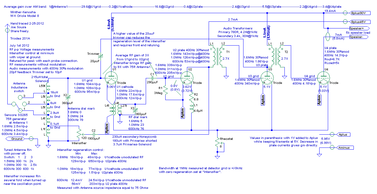
The next schematic for the Oriole 8 shows gains, measured p-p AC voltages, DC currents and voltages, Intensifier operation with 75Ω antenna and Bandwidth. (click to enlarge)
Comparing to the FADA 160A
The next schematic for the FADA 160A Reflex 3-dialer TRF set shows a few reference inductance measurements. Inductances in parenthesis with the opposite winding shorted. (click to enlarge)
The inductances of the FADA 160A and Oriole 8 RF interstage transformers are surprisingly similar, except that the primary inductances of the FADA 160A are larger. The primaries are just a few uH, but the FADA transformers are more tightly coupled as can be seen that the FADA secondary inductance dropped 34% with the primary shorted, while the Oriole secondary inductance dropped only 22%. This explains some of the higher gain of the Neutrodyne stage. It is possible that the choice for looser coupling in the Oriole 8 might have been to enhance selectivity because there are only two tuned circuits in the Oriole 8.
This table summarizes and compares Oriole 8 and FADA 160A gains.
| Winther-Kenosha Oriole 8 | ||||||||||||
| RF | RF | DET | DET | Audio1 | Audio1 | Audio2 | Audio2 | |||||
| Antenna | U1grid | U1cathode | U2grid | U2plate | U3grid | U3plate | U4grid | U4plate | TOTAL | Intensifier min | max | |
| 1.6MHz (mV) | 2,5 | 104 | 22 | 339 | 143 | 340 | 1860 | 4180 | 14300 | 18 | 48 | |
| 1.0MHz (mV) | 4,5 | 109 | 17,6 | 311 | 126 | 18 | 77 | |||||
| 600kHz (mV) | 3,4 | 95 | 12 | 205 | 53 | 12,4 | 24,5 | |||||
| Average (mV): | 3,47 | 102,7 | 17,2 | 285,0 | 107,3 | 16,1 | 49,8 | |||||
| gains | 1 | 29,6 | 0,2 | 16,6 | 0,4 | 2,4 | 5,5 | 2,2 | 3,4 | 3096 | Intensifier gain: | 3,1 |
| RF gain | U1cathode | U1cathode | ||||||||||
| 2,8 | ||||||||||||
| FADA 160A | RF1 | RF1 | RF2 | RF2 | DET | DET | Audio1 | Audio1 | Audio2 | Audio2 | ||
| Antenna | U1grid | U1plate | U2grid | U2plate | U3grid | U3plate | U1grid | U1plate | U4grid | U4plate | TOTAL | |
| 1.0MHz (mV) | 5,3 | 16 | 6 | 83 | 76 | 573 | 60 | 160 | 937 | 2600 | 12200 | |
| 400Hz | 400Hz | 400Hz | 400Hz | |||||||||
| gains | 1 | 3,0 | 0,4 | 13,8 | 0,9 | 7,5 | 0,1 | 2,7 | 5,9 | 2,8 | 4,7 | 2302 |
| RF1 gain | RF2 gain | Reducing DET filament Voltage from 5V to 4.4V | ||||||||||
| 5,2 | 6,9 | doubled detector grid and plate amplitudes |
The greatest surprise in these results was that the voltage gain from grid to plate in the FADA 160A was less than 1x at 1MHz (0.4x and 0.9x). The entire voltage gain for the FADA was actually realized in the step-up tuned transformers, however, if the FADA is not very carefully neutralized, it will oscillate wildly, despite the gain of less than 1 from grid to plate after neutralization. The net RF voltage gains were 5.2 x and 6.9x for the two neutralized RF stages.
Another surprise in my particular FADA 160A was the lack of grid-leak RC network at the detector, which had the grid hard-wired through the grounded RF coil. This made the detector efficiency more dependent on plate and filament voltages. Cutting the filament voltage from 5V to 4.4V doubled detector audio output.
Unlike the Oriole 8, The FADA puts the filament rheostat on the A+ side, thus wasting an opportunity to give a bit of free negative bias to the grids. The detector pot could have tapped the 5V filament bus, instead of the A+ line, because the lack of grid leak network requires a higher grid impedance to match the driving RF tank. The presence of a grid leak resistor grealy reduces the current through a nominally grounded grid, and thus it increases the grid impedance as compared to a hard grounded grid.
It was quite challenging to keep the FADA neutralized and out of oscillations. Finally, I had to add a 0.02uF cap from B+ to A- and the detector plate voltage is best kept at 15V (instead of 22.5V) to avoid any possibility of oscillation. The detector stage is not neutralized and the detector plate filter cap seems insufficient to filter all RF signal. (keep in mind that the Detector output drives the first tube which operates in reflex configuration as first RF amp and first Audio preamp)
I am glad that measuring the Oriole's extraordinary RF cathode follower made me take a close look at the FADA. By the way, my FADA was shipped from the factory with the “Neutrodon” neutralization capacitors soldered in place wide open. The FADA oscillated like mad until I neutralized it by adjusting the “Neutrodons” properly.
During the work in both sets, I found it helpful to clean all socket contacts with a fiberglass pencil brush and also add a drop of DeOxit to all fastened connections. This finally got rid of all noises and intermittents. A poor filament contact can sound just like antenna static, except that it does not go away when the antenna is disconnected. Very good filament pin contacts are needed to carry the 1/4A filament current without contact chatter.
One point from this Oriole 8 vs FADA 160a comparison that is very clear, is how inherently stable the Oriole 8 cathode follower design is, with a similar inductance cathode load as the plate in the Neutrodyne, which demands very careful neutralization for stability.
Final operation of the Oriole 8
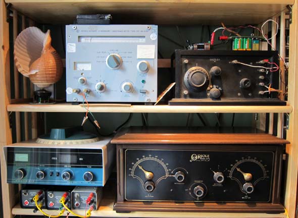 I placed my Oriole on a shelf in my home lab under my BN6100 inductance meter that was used to measure it's inductances. My Crosley 51 sits above it, and my Heathkit MR1010 Direction Finder radio sits to it's left.
Power - The three little cubes under the Heathkit are +/-15V 30mA PR-30 Philbrick power supplies which I wired in series to provide a very quiet source of 45V and 90V "B" voltage for the Oriole 8. The "A" filament power for the Oriole 8 is provided by an unusually quiet 6V 2A switching power supply. This a simple "wall-wart", but has no discernible RF interference on the Oriole 8 operation. The 6V wall-wart and the 90V power are all plugged into one convenient switched power strip.
Loop Antenna - The antenna connection resulted from long term experimentation that I have conducted with large loop antennas. In this case, I made a loop that measures 120" (3m) wide and is 64" (1.6m) tall. This loop is made from Category-5 wire with 4 pairs of insulated conductors that is commonly used for Ethernet installations. I arranged the 4 pairs of insulated conductors into two turns of 4 conductors each, for a total loop inductance of 51uH. The 4 condutors in each of the loop turns function as if they were 4-strand Litz wire. The Q of this loop was measured with the BN6100 as 33 at 315kHz. This extrapolates to a Q around 100 in the middle of the broadcast AM band.
The 51uH inductance turned out to be very suitable to connect to any of the three antenna taps of the Oriole 8, which range in inductance from 3uH to 16uH. Connecting to to tap 3 via the selector switch in the Oriole 8 gives the highest sensitivity, while switching to tap 1 gives the highest selectivity. The detuning by the inductive loading is relatively slight, even in the 16uH tap because these taps are loosely coupled to the total 215uH of the input antenna coil.
This indoor loop antenna is very convenient and seems to be quite sensitive for this 1920's era radio. My outdoor antenna is the vertical coax wire leading to my UHF TV antenna, perhaps 15m high, and is somewhat more sensitive than this big indoor loop. One disadvantage of the loop is that any stations lined up with the loop notch can't be received, but I think I was lucky, in that no stations seem to be lined up direction with the loop notch. The notch is perpendicular to the loop plane. There is also the usual advantage that loops have against picking up electric field man-made intereference. More on loops: Loop replaces Aerial, Active Loop, A few RF interference Measurements, Crystal Radio for AM Karaoke. There is additional content in the German speaking side of the forum. Use "Rahmen Antenne" as search words. I often read these posts with the Google translator.
The selectivity and sensitivity of the Oriole 8 and FADA 160A were comparable, but the Oriole is easier to tune with just two dials.
Shell Speaker - In a parallel project to the analysis and repair of the Oriole 8, I built a very sensitive speaker made from a sea shell I bought in Hawaii last winter and a driver from a sound-powered telephone.
![]() Sound-powered telephones operate without any external power source. The voice creates an electrical signal that is heard in an identical reed type of speaker/microphone transducer. These were developed for military uses as well as for environments where an accidental electrical spark might be dangerous. One byproduct of these tough requirements is that these transducers are very sensitive and are thus highly prized by crystal radio builders.
Sound-powered telephones operate without any external power source. The voice creates an electrical signal that is heard in an identical reed type of speaker/microphone transducer. These were developed for military uses as well as for environments where an accidental electrical spark might be dangerous. One byproduct of these tough requirements is that these transducers are very sensitive and are thus highly prized by crystal radio builders.
In addition to higher sensitivity, the transducers have a better high frequency response at 4kHz than the few horns from the 1920's, that I have heard.
The transducer impedance is 600Ω, so I use the impedeance matching transformer on the left to match to the Oriole output at a 5kΩ setting.
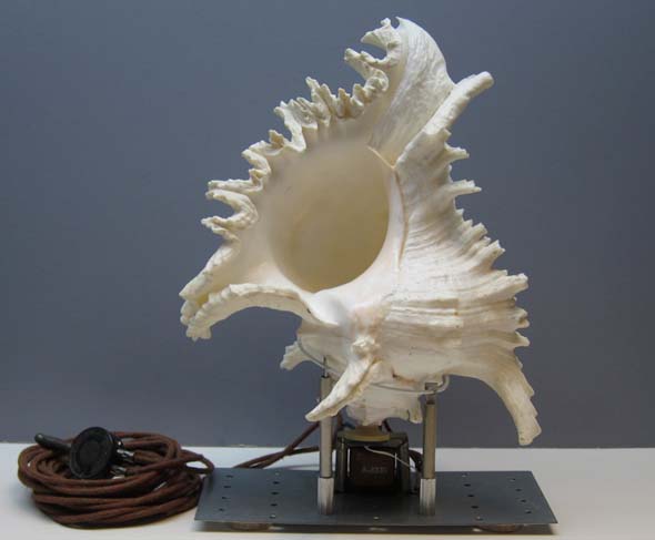
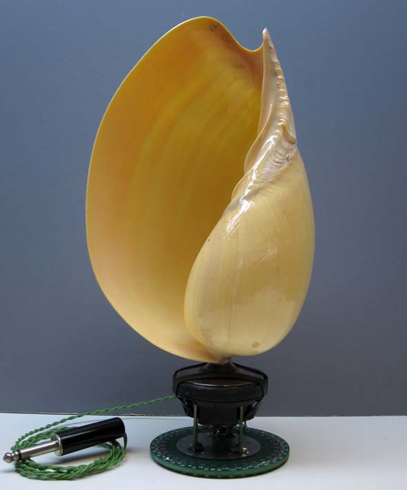
The following show construction details for this shell speaker, along with two more shell variants.
(click to enlarge)
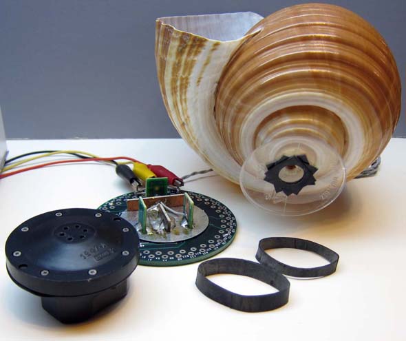
The acoustic interface principle is to present the transducer with a hole that looks like the ear canal. This should give a good acoustic impedance match. I drilled a small hole, about 8mm at the tip of the shell and glued the pedestal of a plastic cut to serve as the interface. Self-adhesive rubber rings seal the accoustic interface around the little holes of the transducer. Two large neoprene rubber bands cut out from old bicycle tires hold the shell and transducer together, but the shell can actually stand on it's own. A small PCb disk serves as the base.
The best sounding of the shells is the first one. All have comparable high frequency response, but the gentle exponential taper of the first shell, it's wide mouth and thin resonant walls make for a very pleasant human void reproduction that is much clearer than a couple of 1920's horns I compared. The central shell has a smaller mouth and very hard walls, so the low frequency response is poorer. The transducer on this shell is also a little modern flat earphone speaker. The shell on the right has a poorer low frequency response, despite the wide opening, because it's exponential progress is more abrupt, which is to say it is a shorter horn.
Best regards,
-Joe
Joe Sousa, 08.Oct.12