Bauplan 1251
Görler, J. K.; Berlin (Meuselwitz, Mannheim, Brühl)
- Country
- Germany
- Manufacturer / Brand
- Görler, J. K.; Berlin (Meuselwitz, Mannheim, Brühl)
- Year
- 1947 ?
- Category
- Kit (Parts plus instruction) or building instructions only
- Radiomuseum.org ID
- 220422


Click on the schematic thumbnail to request the schematic as a free document.
- Number of Tubes
- 6
- Main principle
- Superheterodyne (common); ZF/IF 473 kHz; 1 AF stage(s)
- Tuned circuits
- 6 AM circuit(s)
- Wave bands
- Broadcast, Long Wave and Short Wave.
- Power type and voltage
- Alternating Current supply (AC) / 110; 125; 220 Volt
- Loudspeaker
- Permanent or electro-dynamic (moving coil), system not known yet.
- Power out
- 3 W (unknown quality)
- from Radiomuseum.org
- Model: Bauplan 1251 - Görler, J. K.; Berlin
- Notes
-
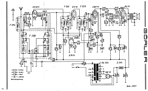
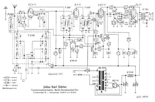
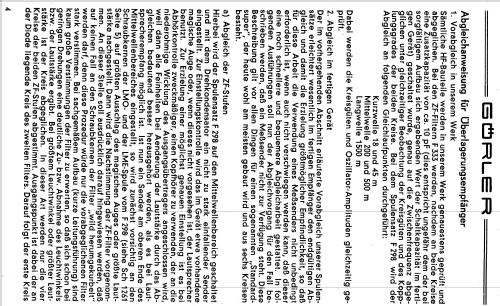
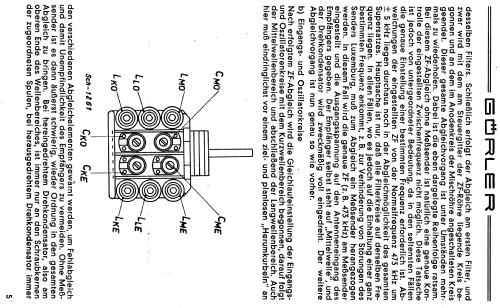
Schaltbild zeigt eine Bauanleitung für einen 6-Kreis-AM-Super mit den Görler-Bauteilen
Das gleiche Schaltbild Sch 1251 vertreibt Hochfrequenz-Werkstätten Meuselwitz (HFWM, ex Görler) mit den baugleichen Teilen
Es ist noch nicht exakt nachgewiesen, ob alle hier aufgeführten Bauteile nach 1946 aus dem Werk Meuselwitz stammen und nur unterschiedliche Bezeichnungen für "West"- oder "Ost"-Deutschland erhielten - oder ob eine Parallelproduktion in Berlin stattfand.
Das Schaltbild 1251a zeigt einen Bauplan für einen 8-Kreis-AM-Super, der zusätzlich ein drittes Bandfilter F333 (ZB1) enthält.
- Source of data
- - - Manufacturers Literature
- Mentioned in
- HFWM-Liste Superspulensatz 1949
- Author
- Model page created by Manfred Rauschen. See "Data change" for further contributors.
- Other Models
-
Here you find 134 models, 108 with images and 118 with schematics for wireless sets etc. In French: TSF for Télégraphie sans fil.
All listed radios etc. from Görler, J. K.; Berlin (Meuselwitz, Mannheim, Brühl)