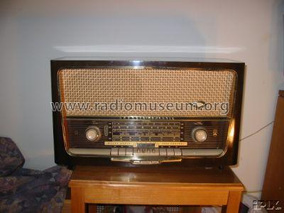
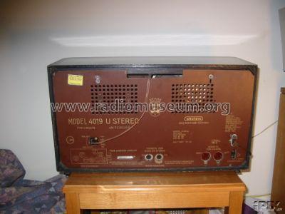
Majestic 4019 U Stereo
Grundig (Radio-Vertrieb, RVF, Radiowerke); Fürth/Bayern
- Paese
- Germania
- Produttore / Marca
- Grundig (Radio-Vertrieb, RVF, Radiowerke); Fürth/Bayern
- Anno
- 1959/1960
- Categoria
- Radio (o sintonizzatore del dopoguerra WW2)
- Radiomuseum.org ID
- 90975
-
- alternative name: Grundig Portugal || Grundig USA / Lextronix
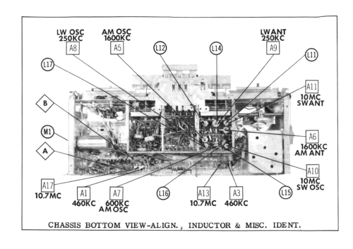
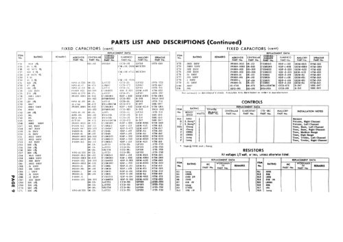
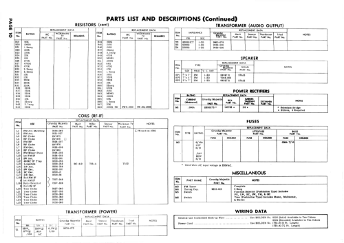

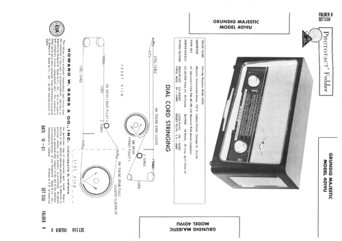
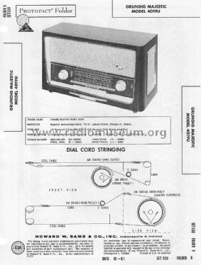
Sams PhotoFact Folder 8, Set 550, DAte 10-61
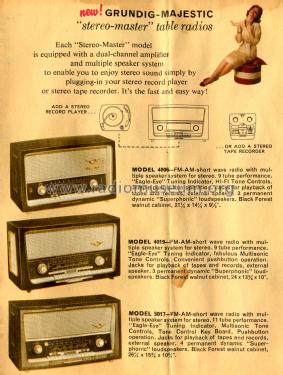
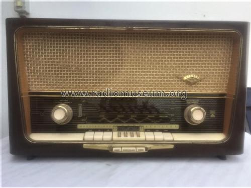
Picture from Grundig Majestic Brochure
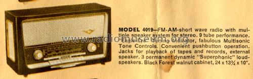
Picture from Grundig Majestic Brochure
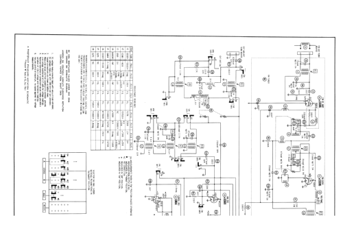
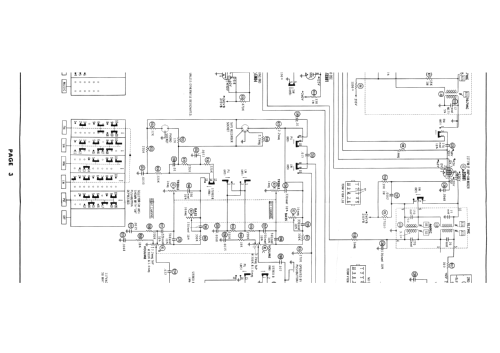
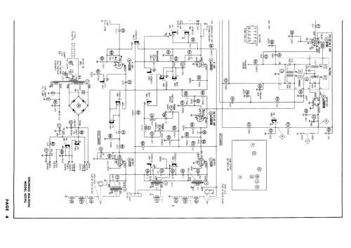
Clicca sulla miniatura dello schema per richiederlo come documento gratuito.
- Numero di tubi
- 8
- Numero di transistor
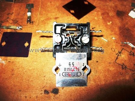
- Semiconduttori
- B250C75
- Principio generale
- Supereterodina (in generale); ZF/IF 460/10700 kHz
- N. di circuiti accordati
- 6 Circuiti Mod. Amp. (AM) 10 Circuiti Mod. Freq. (FM)
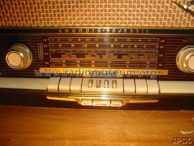
- Gamme d'onda
- Onde medie (OM), lunghe (OL), corte (OC) e MF (FM).
- Tensioni di funzionamento
- Alimentazione a corrente alternata (CA) / 110-120; 220 Volt
- Altoparlante
- 3 altoparlanti
- Materiali
- Mobile in legno
- Radiomuseum.org
- Modello: Majestic 4019 U Stereo - Grundig Radio-Vertrieb, RVF,
- Forma
- Soprammobile con pulsantiera/tastiera.
- Dimensioni (LxAxP)
- 610 x 350 x 250 mm / 24 x 13.8 x 9.8 inch
- Annotazioni
-
UKW 88 - 108MHz.
This is the export version of Grundig Konzertgerät 4019 Stereo.
- Letteratura / Schemi (1)
- -- Original-techn. papers.
- Autore
- Modello inviato da Ernst Erb. Utilizzare "Proponi modifica" per inviare ulteriori dati.
- Altri modelli
-
In questo link sono elencati 6251 modelli, di cui 5496 con immagini e 4255 con schemi.
Elenco delle radio e altri apparecchi della Grundig (Radio-Vertrieb, RVF, Radiowerke); Fürth/Bayern
Collezioni
Il modello Majestic fa parte delle collezioni dei seguenti membri.
Discussioni nel forum su questo modello: Grundig Radio-: Majestic 4019 U Stereo
Argomenti: 3 | Articoli: 11
I have a 4019U that plays very well, but the stereo balance control does not work. After checking all the switch contacts, tubes, capacitors, most of the resistors .Not being familiar with this model, I need some help getting this radio to work properlly.Would someone please help me? Thank you Ross W. Hoff
Ross Hoff, 08.Feb.19
- C58 and C59 values swapped on the Sam's.
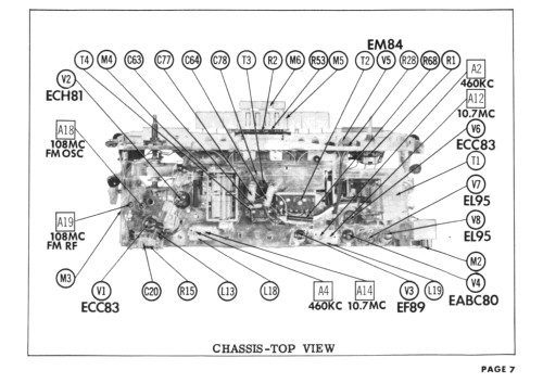
- T4 secondary wire colors swapped. Green is ground and puts speaker SP3 electrically out of phase with SP1. The input to V8 is 180 degrees out of phase with V7.
- Page 7, A4 and A14 swapped.
- Page 7, V1 is not ECC83 (12ax7) but is an ECC85 (6AQ8).
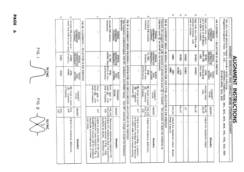
- Page 6 step 6, there is no A15 FM IF adjustment.
- Page 6 step 7, A17 will not to to Zero. Refer to 4019 domestic unit procedure www Radiomuseum.org to confirm that A17 is to be adjusted to Minimum voltage.
- Various capacitors are miss labeled and not identified on page 2.
Happy Restorations,
Paul.
Paul E. Pinyot † 2013, 08.Mar.11
When I first played this radio after the chassis restoration, there was a horrible bass rattle in the oval speaker. When I pulled it for inspection I found all the foam gasket had deteriorated along with the voice coil dust cover.

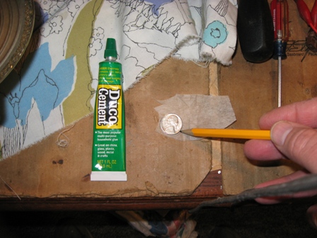


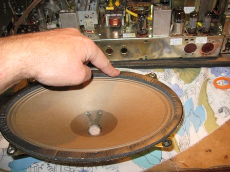
Paul E. Pinyot † 2013, 03.Mar.11