Konzertgerät 5088
Grundig (Radio-Vertrieb, RVF, Radiowerke); Fürth/Bayern
- Hersteller / Marke
- Grundig (Radio-Vertrieb, RVF, Radiowerke); Fürth/Bayern
- Jahr
- 1957/1958
- Kategorie
- Rundfunkempfänger (Radio - oder Tuner nach WW2)
- Radiomuseum.org ID
- 21142
-
- anderer Name: Grundig Portugal || Grundig USA / Lextronix


ebay

�


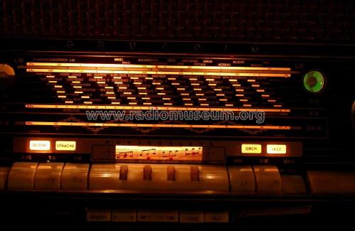
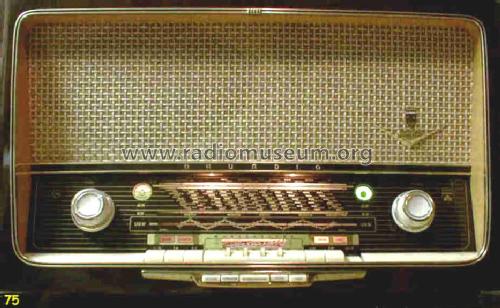
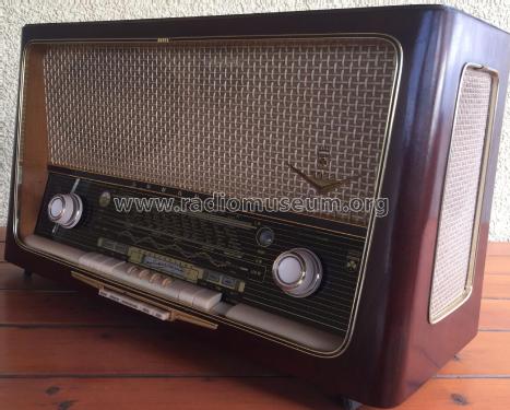
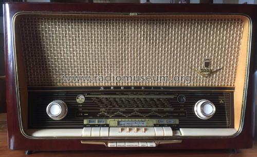
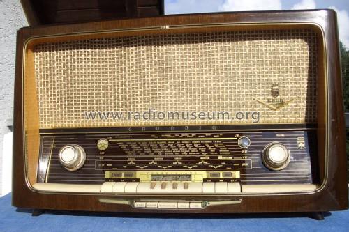
Gerät in Betrieb
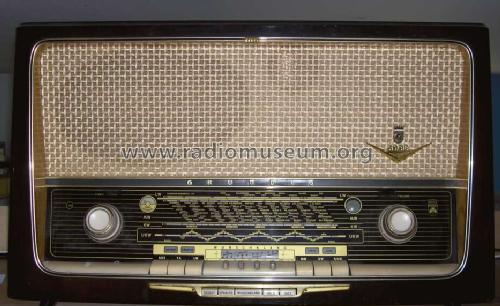


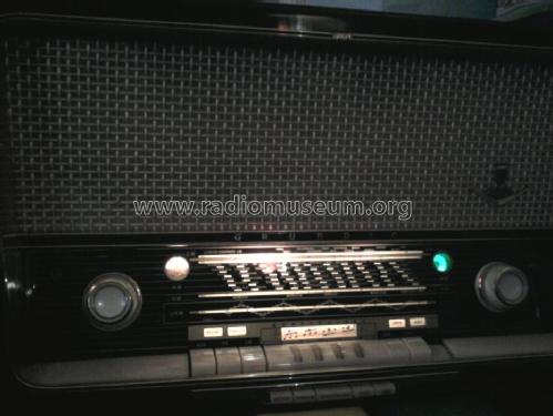
Grundig 5088
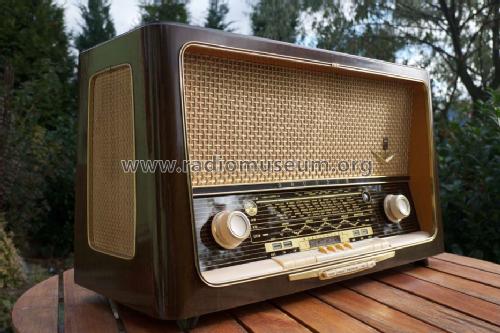
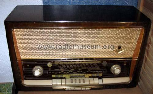
Gerät in restauriertem Zustand, spielt
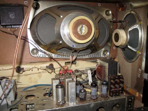


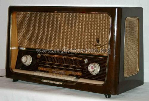
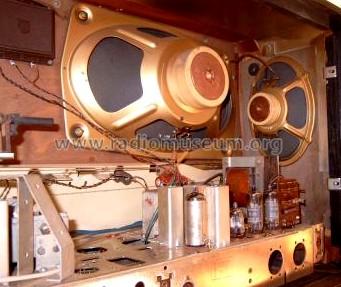
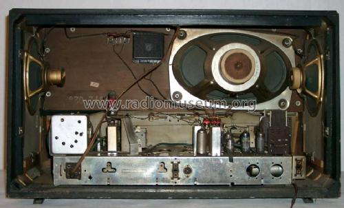
Linke Geräteseite


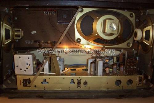
Seriennummer am Chassis
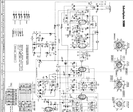
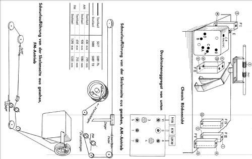
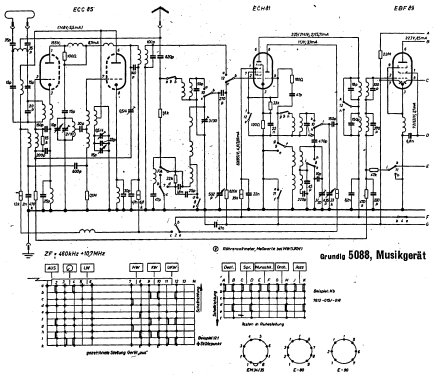
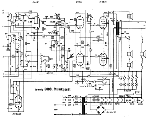
Klicken Sie auf den Schaltplanausschnitt, um diesen kostenlos als Dokument anzufordern.
- Anzahl Röhren
- 8
- Hauptprinzip
- Superhet allgemein; ZF/IF 460/10700 kHz; Reflex
- Anzahl Kreise
- 7 Kreis(e) AM 11 Kreis(e) FM
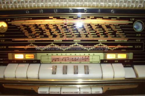
- Wellenbereiche
- Langwelle, Mittelwelle, Kurzwelle und UKW.
- Betriebsart / Volt
- Wechselstromspeisung / 110; 125; 160; 220 Volt
- Lautsprecher
- 4 Lautsprecher
- Belastbarkeit / Leistung
- 7 W (Qualität unbekannt)
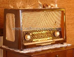
- Material
- Gerät mit Holzgehäuse
Die GFGF Zeitschrift Funkgeschichte bringt interessante Artikel zu Radios, Funkwesen und Medien. Bei Radiomuseum.org finden Sie die vollständigen Hefte früherer Ausgaben als PDF zum Download.
- von Radiomuseum.org
- Modell: Konzertgerät 5088 - Grundig Radio-Vertrieb, RVF,
- Form
- Tischgerät, Tasten oder Druckknöpfe.
- Abmessungen (BHT)
- 670 x 400 x 290 mm / 26.4 x 15.7 x 11.4 inch
- Bemerkung
-
Drehbare Ferritantenne, Wunschklang-Register, Gegentakt-Endstufe.
Bei UKW wird die HF-Vorstufe in Reflexschaltung auch als erste FM-ZF-Stufe verwendet, das ergibt insgesamt 3 FM-ZF-Stufen.
Rückwandangabe 8 AM- und 13 FM-Kreise ist (werbewirksam) falsch.
- Nettogewicht
- 16.9 kg / 37 lb 3.6 oz (37.225 lb)
- Originalpreis
- 448.00 DM
- Datenherkunft extern
- Erb
- Datenherkunft
- HdB d.Rdf-& Ferns-GrH 1957/58
- Literatur/Schema (1)
- -- Original-techn. papers.
- Weitere Modelle
-
Hier finden Sie 6250 Modelle, davon 5496 mit Bildern und 4249 mit Schaltbildern.
Alle gelisteten Radios usw. von Grundig (Radio-Vertrieb, RVF, Radiowerke); Fürth/Bayern
Sammlungen
Das Modell Konzertgerät befindet sich in den Sammlungen folgender Mitglieder.
Forumsbeiträge zum Modell: Grundig Radio-: Konzertgerät 5088
Threads: 1 | Posts: 16
Gentlemen,
I am restoring a Grundig 5088 USA model and need some help with my first non-US radio restoration. I am using a schematic found at www.rad-io.de I have found it to be mostly accurate except for some of the audio frequency circuit architecture. There are differences.
A friend of the family has translated most of the words. So my questions are with the missing information below:
The resistors have the resitance printed on the body and a single color band on one end. What does this band represent and what are the values of the colors?

I have identified three types of fixed capacitors; Paper (Papier), Syrofome (Styrofier?) and Ceramic/mica (Keromic?). However, there are some paper capacitors that have a plastic like blue coating. The schematic clearly identifies these as paper. Is there more to these capacitors? Are they special (i.e., inverse temperature, resonant) capacitors?

Once I have replaced all of the paper and electrolytic capacitors (and the occational off tolerance resistor) RF alignment is next. The IF frequencies (10.7/460) and the transformers are identified. However, there are plenty of other adjustments with no explanation. Where might I find the alignment procedures?
Please forgive me if this information is readily available on the internet. If so, then please recomend an appropriate web site.
Thank you in advance for your time,
Paul.
I am restoring a Grundig 5088 USA model and need some help with my first non-US radio restoration. I am using a schematic found at www.rad-io.de I have found it to be mostly accurate except for some of the audio frequency circuit architecture. There are differences.
A friend of the family has translated most of the words. So my questions are with the missing information below:
The resistors have the resitance printed on the body and a single color band on one end. What does this band represent and what are the values of the colors?
I have identified three types of fixed capacitors; Paper (Papier), Syrofome (Styrofier?) and Ceramic/mica (Keromic?). However, there are some paper capacitors that have a plastic like blue coating. The schematic clearly identifies these as paper. Is there more to these capacitors? Are they special (i.e., inverse temperature, resonant) capacitors?
Once I have replaced all of the paper and electrolytic capacitors (and the occational off tolerance resistor) RF alignment is next. The IF frequencies (10.7/460) and the transformers are identified. However, there are plenty of other adjustments with no explanation. Where might I find the alignment procedures?
Please forgive me if this information is readily available on the internet. If so, then please recomend an appropriate web site.
Thank you in advance for your time,
Paul.
Paul E. Pinyot † 2013, 25.Jan.05