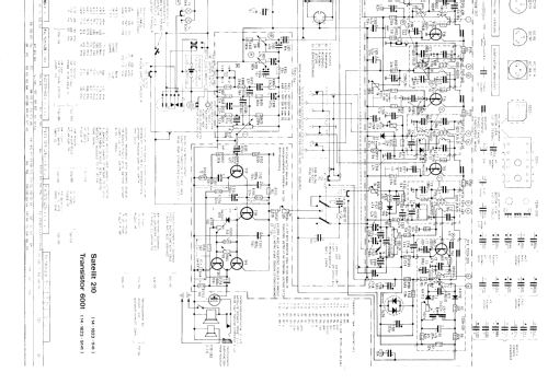
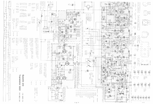
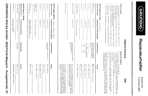
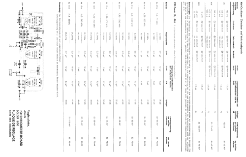
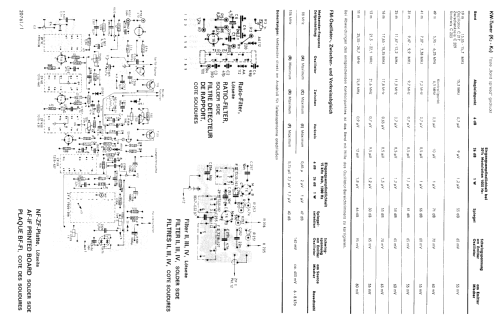
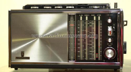
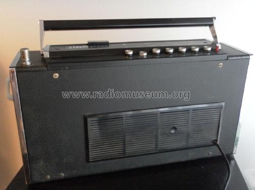
Satellit Transistor 6001 Skala ohne Sendernamen
Grundig (Radio-Vertrieb, RVF, Radiowerke); Fürth/Bayern
- Pays
- Allemagne
- Fabricant / Marque
- Grundig (Radio-Vertrieb, RVF, Radiowerke); Fürth/Bayern
- Année
- 1969–1971
- Catégorie
- Radio - ou tuner d'après la guerre 1939-45
- Radiomuseum.org ID
- 2231
-
- alternative name: Grundig Portugal || Grundig USA / Lextronix


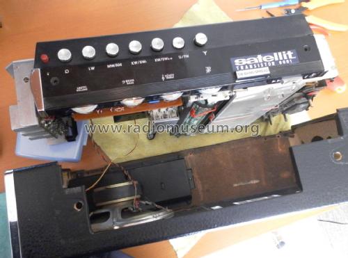
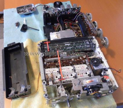
This one of my best Sattelit. It is NEW!!


Cliquez sur la vignette du schéma pour le demander en tant que document gratuit.
- No. de transistors
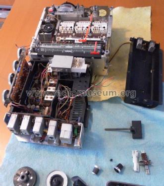
- 21
- Principe général
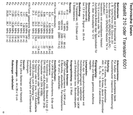
- Super hétérodyne, conversion double ou triple; FI/IF 1850/460//10700 kHz; 2 Etage(s) BF
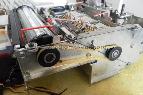
- Circuits accordés
- 13 Circuits MF (FM)
- Gammes d'ondes
- PO, GO, plus que 2 x OC et FM
- Tension / type courant
- Piles sèches / 6 × 1,5 Volt
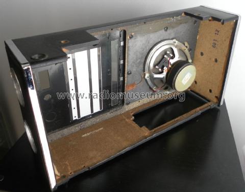
- Haut-parleur
- 2 HP
- Puissance de sortie
- 2 W (qualité inconnue)
- Matière
- Cuir / canvas / plastique mais autre matériel en dessous!
- De Radiomuseum.org
- Modèle: Satellit Transistor 6001 [Skala ohne Sendernamen] - Grundig Radio-Vertrieb, RVF,
- Forme
- Portative > 20 cm (sans nécessité secteur)
- Dimensions (LHP)
- 440 x 260 x 120 mm / 17.3 x 10.2 x 4.7 inch
- Remarques
-
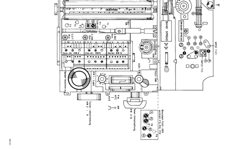
Skala ohne Sendernamen.
14 Kurzwellen-Bereiche, Langwelle bis 420 kHz; AFC und FET-Mischer für UKW; Feldstärke-Anzeige; KW = Doppelsuper; Anschluss an 6-V- bzw. 12-V-Autobatterie über entsprechendes Autobatteriekabel; Netzbetrieb mit eingesetztem, herausnehmbaren Netzteil oder Betrieb aus dryfit-PC-Akku und Netzteil TN14 möglich.
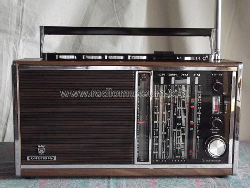
Siehe auch Satellit 210 Transistor 6001.
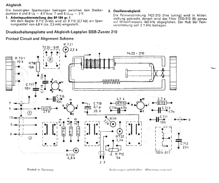
Anschluß für den SSB-Zusatz 2000.
Jeder Transistor-Typ nur einmal gelistet.
- Poids net
- 6.7 kg / 14 lb 12.1 oz (14.758 lb)
- Source
- Handbuch VDRG 1969/1970 / Radiokatalog Band 1, Ernst Erb
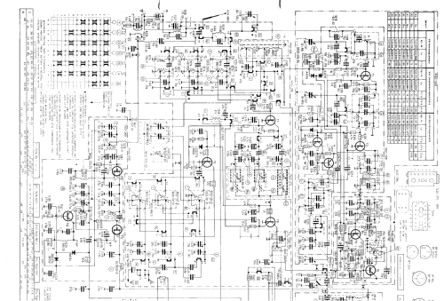
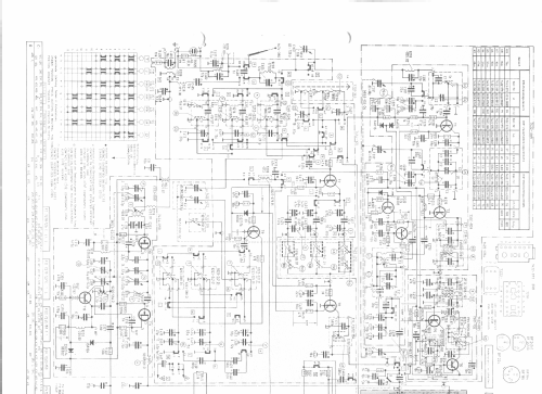
- Schémathèque (1)
- -- Original-techn. papers.
- D'autres Modèles
-
Vous pourrez trouver sous ce lien 6221 modèles d'appareils, 5457 avec des images et 4220 avec des schémas.
Tous les appareils de Grundig (Radio-Vertrieb, RVF, Radiowerke); Fürth/Bayern
Collections
Le modèle Satellit fait partie des collections des membres suivants.
Contributions du forum pour ce modèle: Grundig Radio-: Satellit Transistor 6001
Discussions: 4 | Publications: 25
Guglielmo Russo, 05.Nov.15
Hi!
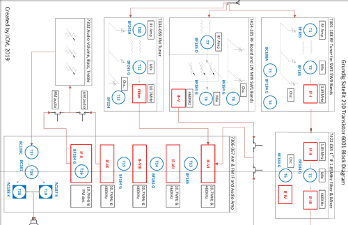
For all Satellit enthusiasts I have published a simplified block diagram that I hope will help on reading/interpret the original schematic diagram.
It has not been a simple job since the 210 is indeed quite complex, but at end I accomplished what I had in mind.
I have tried to keep the position in the functional diagram as close as possible similar with respect to the original schematic. This should also help you on cross-checking the two documents.
As all things produced in spare time, it is possible the document is not 100% accurate, in that case I will appreciate your feedback and comments to improve it.
You can find the document in the schematic section of the Grundig Satellit 210, file name is:
d_grundig_satellit210_block2_1.pdf
Alessandro.
for your convenience, I've included a direct dowload link. Enjoy.
Pièces jointes
- click here to download (180 KB)
Alessandro Capitani, 09.Oct.08
What are other replacement light bulbs that can be used for this radio, that are OEM, and where can they be purchased?
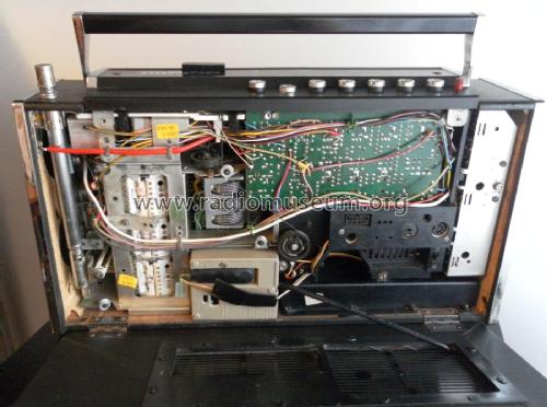
Other than using an eraser (for soft grafite) to clean the drum and using a cremolin based contact cleaner, what are other things that should be done for maintenance of this solid state master piece of 20'th century technology?
Omer
BTW The antenna for the Grundig Satellit 800 uses the same antenna as the 210 and can be purchased from Eton, USA.
Omer Suleimanagich, 09.Aug.05
Zweites Problem: ich wage nicht das Chassis auszubauen, weil ich nicht weiß wie die seitlichen Bedienknöpfe für KW-Abstimmung und Trommeltuner und auch die Skalenseile darauf reagieren und wie der Ausbauvorgang ablaufen muß. Vielleicht hat jemand Erfahrung mit diesem Gerät, aber auch Serviceanleitung und Schaltschema würden weiterhelfen. Vielen Dank im Voraus.
Gerhard Heigl, 17.Aug.04