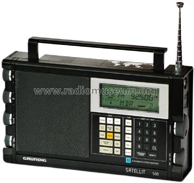
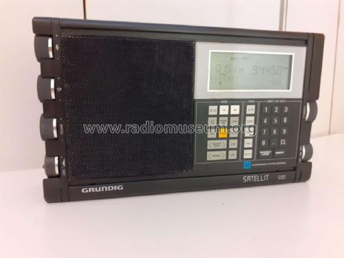
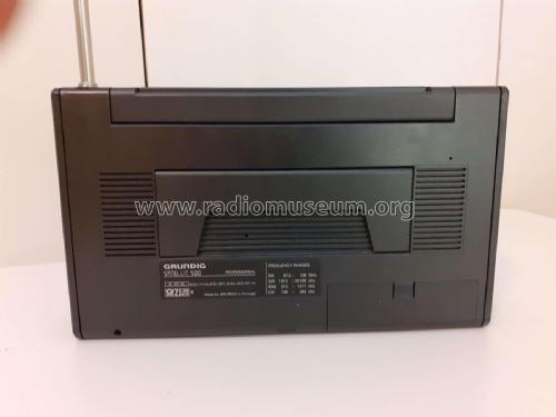
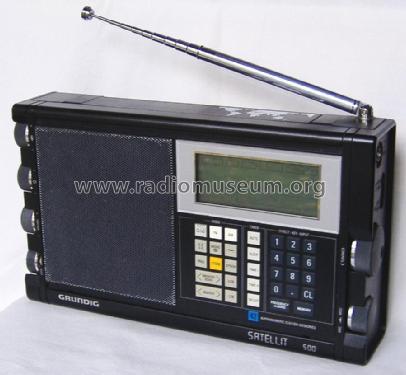
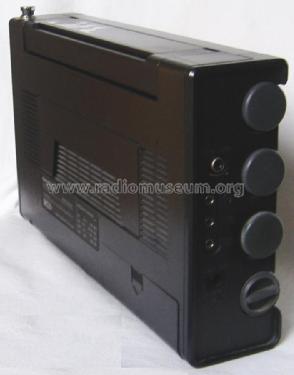
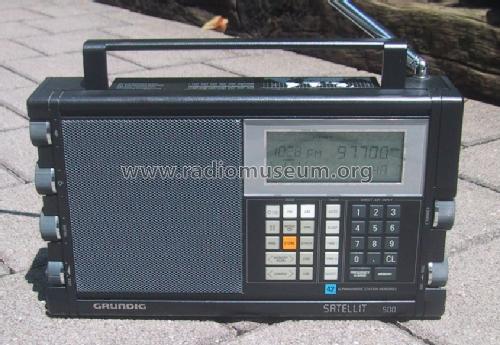
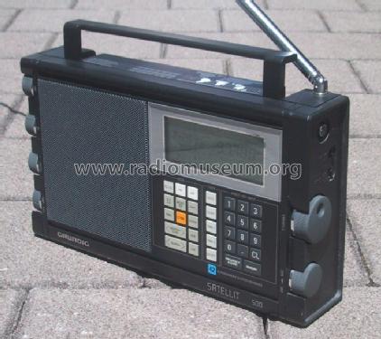
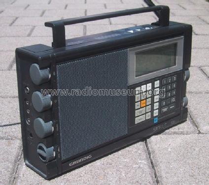
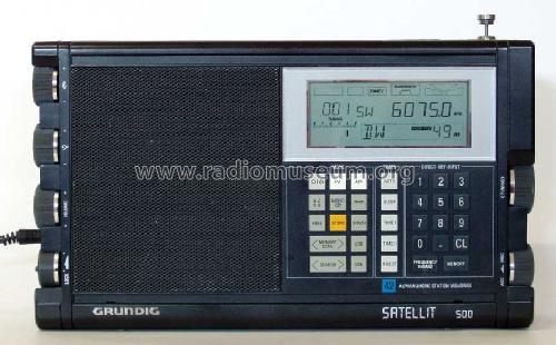
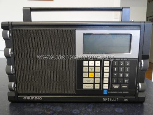
Satellit 500 International, Professional
Grundig (Radio-Vertrieb, RVF, Radiowerke); Fürth/Bayern
- Paese
- Germania
- Produttore / Marca
- Grundig (Radio-Vertrieb, RVF, Radiowerke); Fürth/Bayern
- Anno
- 1989–1991
- Categoria
- Radio (o sintonizzatore del dopoguerra WW2)
- Radiomuseum.org ID
- 73729
-
- alternative name: Grundig Portugal || Grundig USA / Lextronix


Radio Dreams

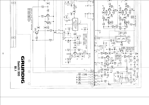
Grundig Satellit 500


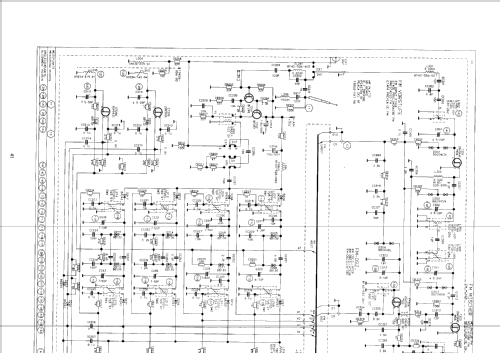
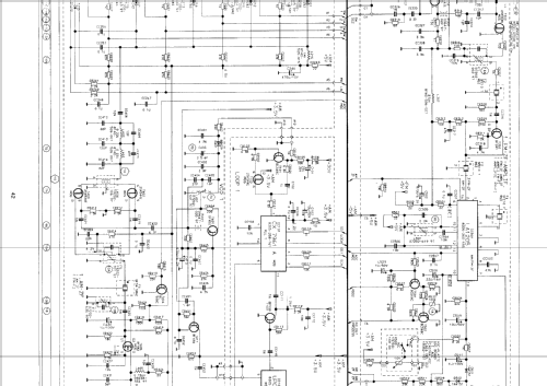
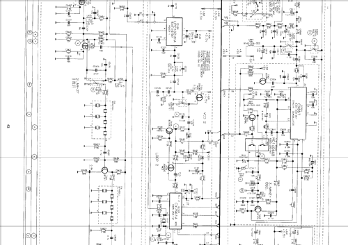
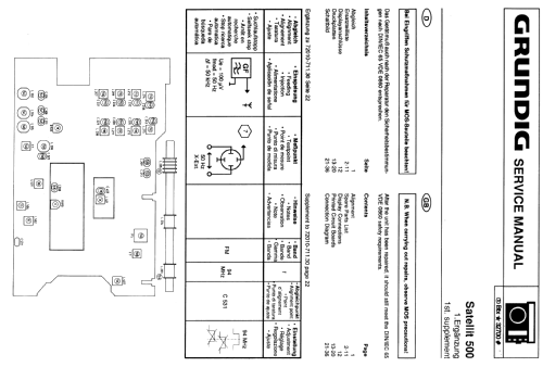
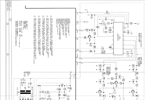
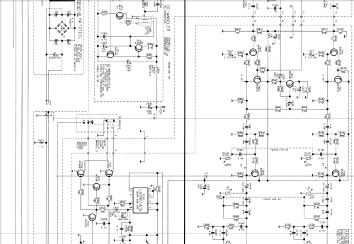
Clicca sulla miniatura dello schema per richiederlo come documento gratuito.
- Numero di transistor
- A semiconduttori.
- Semiconduttori
- Principio generale
- Supereterodina a doppia / tripla conversione; ZF/IF 10700/450 kHz
- Gamme d'onda
- Onde medie (OM), lunghe (OL), piú di 2 gamme di onde corte (> 2 x OC) e MF (FM).
- Tensioni di funzionamento
- Rete / Batterie (ogni tipo)
- Altoparlante
- AP magnetodinamico (magnete permanente e bobina mobile) / Ø 10 cm = 3.9 inch
- Materiali
- Plastica (non bachelite o catalina)
- Radiomuseum.org
- Modello: Satellit 500 [International, Professional] - Grundig Radio-Vertrieb, RVF,
- Forma
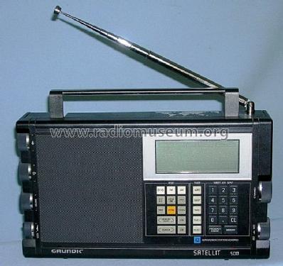
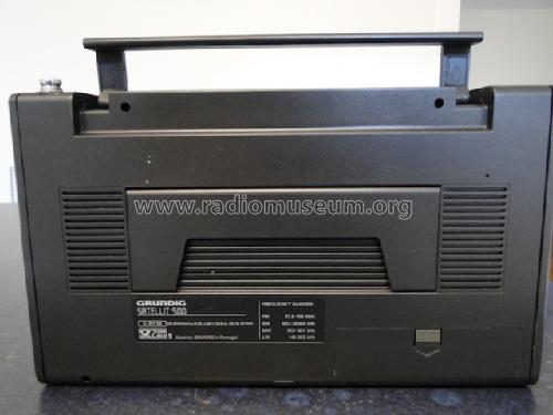
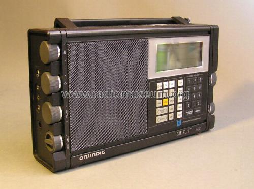
- Apparecchio portatile > 20 cm (senza la necessità di una rete)
- Dimensioni (LxAxP)
- 304 x 178 x 66 mm / 12 x 7 x 2.6 inch
- Annotazioni
-
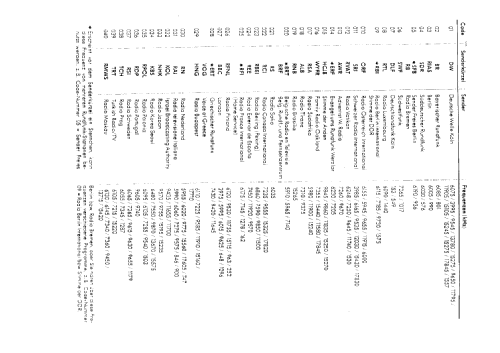
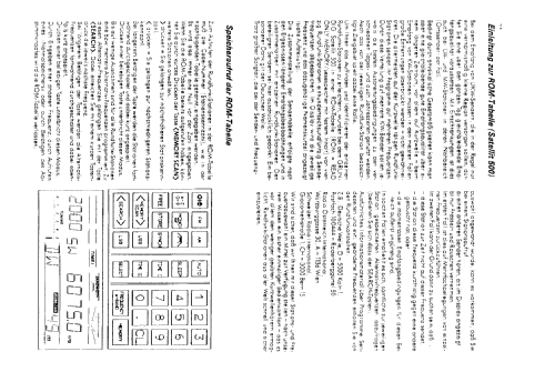
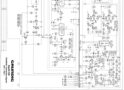
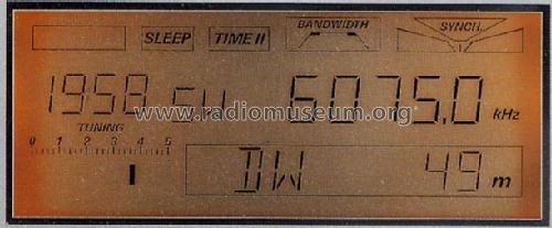
Synchrondemodulator, ROM-Tabelle zur Senderspeicherung.
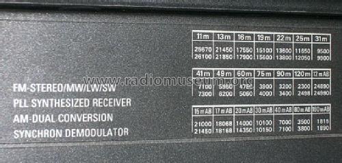
KW-Bereich:
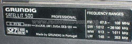
Satellit 500 professional: 1612 - 26100 kHz,
Satellit 500 international: 1612 - 30000 kHz.2 Ausführungen:
Satellit 500 international
♦ bis Geräte Nr. 803001
♦ ab Geräte Nr. 803002.Satellit 500 Professional
♦ bis Geräte Nr. 806691
♦ ab Geräte Nr. 806692.Made by Grundig Portugal.
Siehe auch Satellit 500 ITALIA mit anderen Frequenzbereichen.
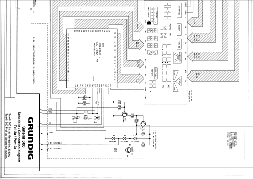
- Peso netto
- 1.8 kg / 3 lb 15.4 oz (3.965 lb)
- Prezzo nel primo anno
- 700.00 DM
- Fonte esterna dei dati
- Roeder, Die Satellit Story, Verlag Siebel
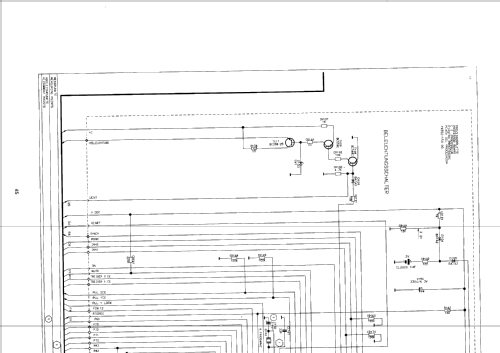
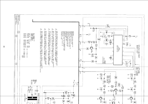
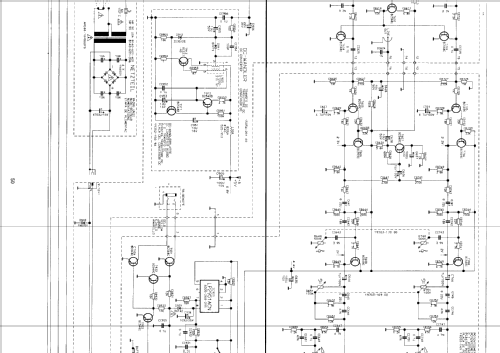
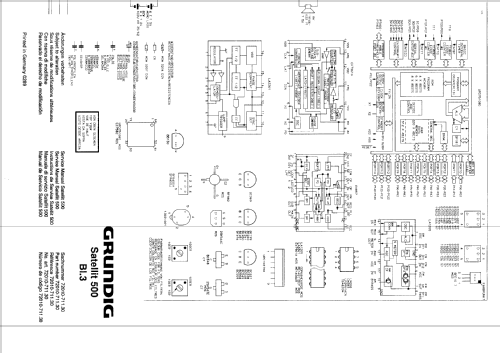
- Letteratura / Schemi (1)
- -- Original-techn. papers.
- Autore
- Modello inviato da Roland Müller. Utilizzare "Proponi modifica" per inviare ulteriori dati.
- Altri modelli
-
In questo link sono elencati 6218 modelli, di cui 5451 con immagini e 4214 con schemi.
Elenco delle radio e altri apparecchi della Grundig (Radio-Vertrieb, RVF, Radiowerke); Fürth/Bayern
Collezioni
Il modello Satellit fa parte delle collezioni dei seguenti membri.
- Martin Bösch (CH)
- Karl-Heinz Entrich † 7.21 (D)
- Antonio Fautilli (I)
- Martin Fichtinger (A)
- Rainer Friedrich (D)
- Wilfried Hofmüller (A)
- Gerhard Härtl (D)
- Wolfgang Lohrie (AUS)
- Jose Mesquita (P)
- Fred Overbeek (NL)
- Rudolf Pirker † 1.7.21 (A)
- Jaroslav Pochyly (CZ)
- Museum Roggenhofer (A)
- Dieter Schulte-Kulkmann (D)
- Sándor Selyem-Tóth (H)
- Holger Struthoff (D)
- Danko Tkalec (HR)
- Gerhard Weiss (D)
- Axel Woebker (D)
Musei
Il modello Satellit può essere visto nei seguenti musei.
Discussioni nel forum su questo modello: Grundig Radio-: Satellit 500
Argomenti: 8 | Articoli: 23
My recent acquisition of the Sat 500 came with a dead CL2020-1HF backup battery.
No wonder, my unit have several components with date codes of June-1991, so the radio was manufactured most probably at the end of 1991. The battery would not survive 21 years in service.
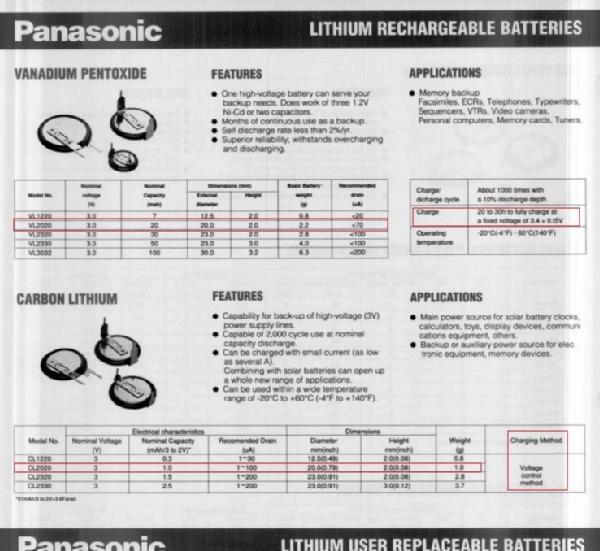
Some interesting facts about the CL2020 rechargeable battery:
- This is a Secondary Lithium-Carbon Battery (CL) type
- Energy density: of 4.0 Wh L.exp-1
- Nominal voltage: 3V
- But able to operate from 2V to 3V
- Nominal capacity: 1.0 mAh
- Continuous Discharge drain: From 1 uA to 5 mA
- Dimensions: diameter 20 mm x height 2 mm
- Weight: 1.9 g
- Long term charge and discharge ability
- Recommended charging method: Voltage control
It seem that the CL2020 is out of production, but the currently available VL2020-1HF model, despite having different charge and discharge behavior, will probably work as a replacement.
The VL2020 characteristics share with the CL2020 the same physical size, nominal working voltage, and ability to run under continuous charging. All the other parameters looks to be different:
- This is a Lithium-Vanadium Oxide Secondary Battery (VL) type
- Energy density: 100-140 Wh L.exp-1
- Nominal voltage: 3V
- Flat 3V operation behavior
- Cut-off voltage: 2.5V
- Nominal capacity: 20mAh
- Continuous Discharge drain: Standard at 70 uA
- Dimensions: diameter 20 mm x height 2 mm
- Weight: 2.2 g
- Excellent overcharge withstanding characteristics
- Recommended Continuous charging voltage:
- 3.25 - 3.55 V
- Typical 3.4V +/-0.15V over a 200 Ohm series resistor
- Typical 1.5 mA charging current
- Recommended Continuous charging voltage:
The SRAM load, a CDP68HC68R2E type, is able to run aty a VDD of 3 to 5.5V, with a minimum data retention voltage of 2V.
I see why the CL2020 was chosen here, as it can run as low as 2V, enough to be able to feed retention current to the SRAM in this condition. The same can not be said of the VL2020 that will cut-off at 2.5V.
I have ordered a VL2020-1HF (1HF relates to the soldered pins mechanical shape, identical to the original).
I will install it without circuit modification to see the result. I guess it will take long time to charge due to the much higher capacity and the now inadequate CR139 1K series resistor that will drop too much voltage limiting the charging current well below the recommended 1.5 mA.
If it does not fully charge to the nominal value, I will remove the voltage divider network (CR139 1K and CR141 12K) to raise the voltage from 3.2V to the VDD1 3.5V.
The charging voltage drops at least 150 to 200 mV on the D104 BAT42 schottky diode, so my guess is that the original design applies around 3.05V (3.2V - 150mV) to the CL2020. I assume Grundig followed the recommendation to charge for voltage control.
Now, 3.05V looks short as a charging voltage for the VL2020, so, by removing the voltage divider resistors, the VL2020 will see around 3.35V (3.5V - 150mV) wich looks to be inside the recommended charging voltage limits.
(to be continued after testing with the VL2020 battery)

Note: The Panasonic Batteries catalog from Oct-1991 published by their Battery Products Department in Mississauga Ontario Canada that can be downloaded from datasheets archival website, lists both battery types (CL2020 and VL2020) with some specification data. Other battery details were taken from google books, namely "Handbook of Battery Materials" by Jurgen O. Besenhard (Wiley-VCH), and Handbook of Battery Materials 2nd edition, same author plus Claus Daniel (also Wiley-VCH).


Jose Mesquita, 25.Sep.22
20-Sept-2022: I have updated this article, following my acquisition of a Sat 500 unit.
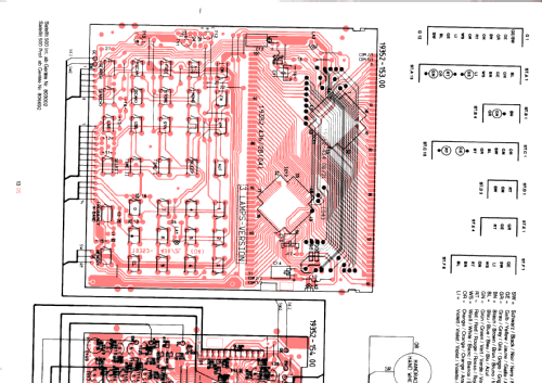
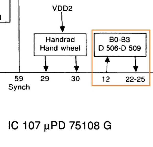
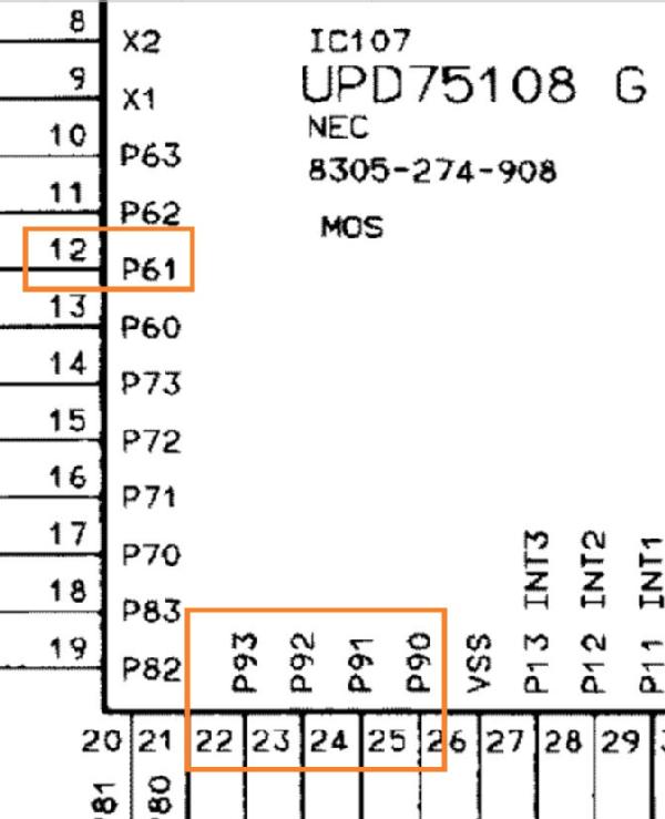
According to the service manual with P/N 72010-711.31 - Printed in Germany 1189, the design uses a set of diode bridges to set between the International, Professional and Italian versions.

Where Bridge = 1 means diode installed
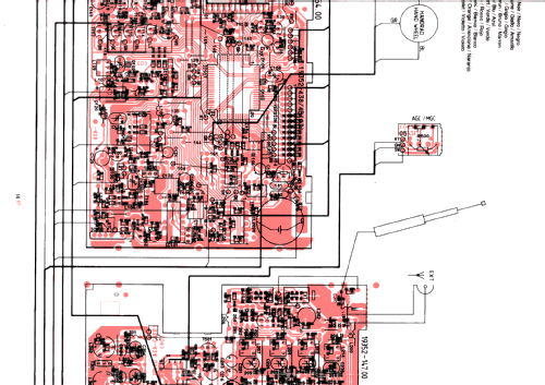
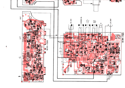
The above table was created based on the Service Manual P/N 72010-711.31 mentioned before, where the Receiver PCB having the Diodes Bridges shows the P/N 19352-434.01/4B(02).
It seems that later productions of this radio model uses updated versions of the Hardware and Firmware, where the Diode Bridges setup can be different from the original production.
This is the case with my radio unit, a INT version, using a Receiver PCB with a later P/N 19352-434.01/2L(05) revision.
Here the INT version uses the setup: B3 = 1, B2 = 1, B1 = 1, B0 = 0, so the bridge B2 (D508) setup is set differently from the original setup listed above.
I confirmed this setup change in my radio unit, by entering the Testmode mode, and saw the Version = INT and the diodes bridges setup = 1110.
After opening the radio to inspect the PCB, I saw that all four diodes are installed, but the diode D506 (bridge B0) was cut at the cathode leg.
According to the service manual, the Test Mode also shows the current Bridge Diodes setup corresponding to the model version. To invoke the Test Mode, turn off the radio, type in the code 050251, press STORE to see the version, then press STORE again to see the Diodes Bridges.


Later Receiver PCB version p/n 19352-434.01/4B(03) P-19352-147.94 19352-434.01/3L)05), some components dated as of 1991, using 3-Lamp (2-lamp on LCD display, 1-Lamp on Keyboard), where the Testmode shows version = INT and the diodes bridges setup = 1110.

Jose Mesquita, 10.Sep.22
Hallo
Habe im bekannten Auktionshaus eine Sat.500 und 700 ersteigert,zur Rep des 700 später.
Radio mit Netzteil 12V angeschlossen eingeschaltet,Radio spielt aber Wackelkontakt in der
Netzteilbuchse und Beleuchtung keine Funktion.
Schaltpläne und Bedienunganleitungen im Internet für beide Geräte bestellt (Kopien).
Radio komp. zerlegt Netzteilbuchse Lötstellen offen Leiterbahnen unterbrochen durch ausdünstung
Batterien nachglötet Leiterbahnen rep.
Birnchen ausgelötet in Ordnung,Transistor T111 defekt erneuert Bel. in Ordnung wahr mir aber zu
dunkel,im Internet gibt es einen Artikel Umrüstung auf LED.
3mm LEDs besorgt Orange 7800mcd 34 Grad mit Vorwiederstand 180Ohm eingebaut sieht Super aus.
Ebenfalls habe ich die Stützbatt. gewechselt mit einer Panasonic VL-2020-HFN.
Ebenfalls habe ich das MPX Signal vor dem Stereodecoder mit einem abgeschirmten dünnen Kabel
nach aussen geführt ohne ein Loch zu bohren,den ich habe 2 selbst gebaute RDS-Decoder,funktioniert
allles super, Bericht über den Sat.700 folgt später.
Gruss
Gerhard Härtl
Allegati
- Grundig sat 500 umbau (202 KB)
Gerhard Härtl, 08.Feb.19
ich besitze die 3-Lampen-Version des Satellit 500. L2 (rechts vom Display bei Draufsicht) war defekt. Ich habe es durch eine Glühbirne 5V 60 mA ersetzt. Bei Betrieb leuchtet L2 nun sehr schwach, es liegen nur 2,4 V an. Die beiden anderen Glühlampen erscheinen normal hell. Lt. Schaltbild liegen alle 3 Glühbirnen in Reihe, div Transistoren steuern die Spannung/Stromverteilung. Wo muss ich die Suche ansetzen ?
Roland Langfeld, 06.May.17
UKW wird nur noch verzerrt wiedergegeben und der Empfang wird immer schwächer. Ich habe die Umschalter im Antenneneingang in Verdacht, Oxydation, oder sonst einen Transistor im Eingangsverstärker. Manchmal kommt UKW aber plötzlich wieder kräftig und stark.
Ich reinige als erstes die Teleskop-Antenne und öle sie. Keine Verbesserung. Ich sprühe die Schalter der Antenne extern/intern und Nah/Fern. Keine Verbesserung. Beim Drücken um die Spule L301 mit einem Schraubenzieher kommt es zu merklichen Empfangsveränderungen: lauter, aber auch verzerrter; manchmal, aber nicht stetig; nicht eindeutig hervorgerufen vom galvanischen Kontakt. Mehr aus Ratlosigkeit bewege ich die Steller der Trimmer C 308 und C 311. Die Empfangsverbesserung tritt sofort auf und ist bleibend. Sind die C also irgendwie fehlerhaft? Oder macht nur der Läufer wieder Kontakt, und war er vorher ohne Kontakt? - Wer weiss es, aber UKW läuft - laut, sauber und schön, wie ehedem.
Bruce Cohen, 01.Jan.16
Giovanni Bruzzi, Italy brought this article. But he used copy & paste to bring it in from an other editor (like word) which did only show his first sentence (for certain browsers - like IE 8):
"This article was written by Ylo Mets, I'm only reporting it because I've found interesting."
The correct way is to copy (yes) and to place the curser into the field (yes) but then to click the pictogram above with the "T" instead of using "paste" (for instance by control/v). The "Text button" is the 3rd after the scissors.
The original post from Giovanni did even not allow a second post ... Well, after writing that: The whole can be seen at least with Mozilla Firefox - but I let it be to be able to analyze the text codes one day.
Ylo Mets
Institute of Chemical Physics & Biophysics,
Estonia
Grundig Satellit 500 is known for its inferior synchronous detector. There are two problems with it:
1) excessive distortion, especially in the SSB mode, and
2) its synchronous SSB mode cannot be activated via the keyboard and processor.
For the excessive distortion there are two reasons:
1) too high DC voltage at the output of the detector chip CX857 (this may have slight effect on normal AM also), and
2) low frequency (50-200 Hz) feedback to the VCO of the first mixer (this affects only SSB).
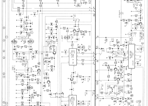
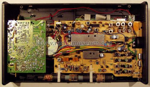
The voltage at the outputs can be corrected in two ways. The easier way is to connect a 24-33 kohm resistor from each output (pins 7and 8) to ground. If you don't have the service manual, the correct points are positive pins of electrolytic capacitors C825 and C826. These capacitors can be found next to the larger shielded box on the RF board, on the side close to the loudspeaker. After installing these resistors the suppression of the unwanted sideband improved in my receiver from 14 dB to 20-26 dB, and I think the distortion is reduced too.
The correct way to do this would be to install two omitted components: one 1N4148 diode in place of a jumper under the metal shield of the detector, and one 33 kohm chip resistor from pin 7 of the chip to ground (there is a place for it on the board). These will have similar effect, perhaps result in slightly better unwanted sideband suppression in SSB mode without additional balancing (as described later). These components are shown on the factory test circuits of the chip and also in the article on synchronous detection by Mike Gruber in QEX, Sept. '92, pp. 9-16.
The feedback from the audio stages to the frequency of the first mixer oscillator can be reduced by connecting a 2000 microfarad or larger capacitor from the AM +3.5 V to ground (pin 11 in connector A). This reduces also the hum in synch mode, when operating off the mains. The better way could be building a separate better 3.5 V regulator and switch it with AM +5V.
This could improve also the operation of the synch detector with NiCads, which seem to have a bit too low voltage now.
For switching the detector to selectable sideband synchronous mode the pin 3 of connector C on the RF board must be grounded and the wire from the pin 4 of connector B must be disconnected.
This can be done with a switch with two groups of contacts. This switch will then affect only the USB and LSB mode. With the switch activated the SSB mode will mean synchronous SSB. The ground connection can be done via 1 kohm resistor, this avoids problems in case of false connection, and also reduces extra interference from the processor. The detector circuit uses the phasing method to select one sideband, and therefore the phase noise of local oscillators creates clearly audible background (about 20 dB below audio). Also, the shielded oscillators exhibit strong microphone effect, resulting in audio feedback at higher volume.
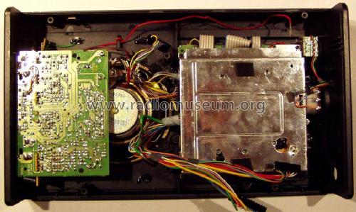
Some hints for opening: the best screwdriver is Pozidrive #1.
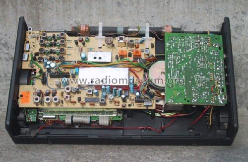
Ordinary Phillips does not fit well, and the screws are quite tight for the first few times to unscrew. The back cover should be lifted at the bottom side, there are plastic hooks at the top side. The RF board can be removed completely after unscrewing the 5 screws and unplugging all connectors. There MAY be an extra capacitor soldered between the RF board and the shield of the processor unit, in the vicinity of the antenna socket. It must be then unsoldered too.
The board is manufactured using surface mount components, so certain caution and fine tipped soldering iron is necessary.
Care must be taken also when soldering the connector wires.
These wires go directly to the microprocrssor pins, so static and other voltage differences between the tools and the radio should be avoided. The simplest way is to disconnect the radio from everything during soldering.
The procedure should be undertaken only if you are sure that your detector is defective too. This can be determined by viewing the suppressed sideband signal of about 500 Hz with an oscilloscope connected to line output, it must be severely distorted
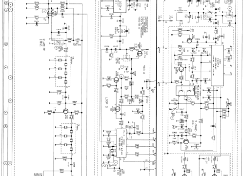
The unwanted sideband rejection can be further improved, but for this the service manual, a signal source (signal generator or a transmitter with clean carrier) and an AC voltage meter or oscilloscope is needed. The procedure is balancing the summing resistors after the audio phase shift circuits. Resistors in question are CR834/CR832 for LSB and CR833/CR831 for USB.
The results on my receiver are following (the frequency of the best suppression depends on actual component values in the phase shifters and is probably different for other units):
Freq. [kHz] USB [dB] LSB [dB]
0.2 15 14
0.5 16 15
1.0 26 24
1.6 48 42
2.0 36 36
2.5 29 28
3.0 25 24
3.6 22 20
For proper balance CR834 was reduced by 10% and CR833 by 20%, but I am sure this is different on each sample. The best suppression value says also something about the distortion.
WARNING: you repeat these procedures at your own risk. Any warranty will be void after these modifications.
Ernst Erb, 23.May.09
I had to delete here because there were too many Word commands which disturbed the system - at least for Windows Explorer which wanted to execute "ietag.dll" for showing the model page. I repeated the content without word commands.
EE Jan. 17, 2014
Giovanni Bruzzi, 19.May.09
Vielleicht kann mir hier jemand weiterhelfen - meine sehr mangelhaften, selbst erworbenen Elektronik-Kenntnisse beschränken sich fast ausschliesslich auf Röhrentechnik .....
Das mir vorliegende Gerät zeigt keine Regung mehr - weder mit Batterien noch mit ext. Netzteil(en). Es wird aber doch ein gewisser (konstant bleibender) Strom aufgenommen. Ein Verhalten, das mich etwas an das Verhalten z.B. eines Satellit 600 ohne Stützbatterie erinnert.....
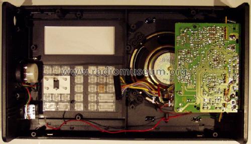
Da ich zuerst die Funktion der internen Spannungsaufbereitung kontrollieren wollte, bin ich nun auf ein Bauteil gestossen, das ich nicht identifizieren kann und das m.E. auch im Schaltplan nicht auftaucht (siehe Bild).
Eingelötet ist es auf der Lautstärkeregler-Platine und neben dem Bauteil ist aufgedruckt "Accu". Handelt es sich hier ev. wirklich um einen (heute defekten) Accu? Aufgrund der Bauart und Grösse kaum zu glauben, aber - was ist es denn und wofür ist es?
Besten Dank für fachkundige Hilfe!
Freundliche Grüsse, Walter Haring
Allegati
Walter Haring, 28.Mar.05