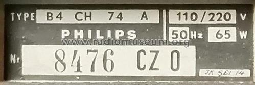
B4CH74A
Philips - Schweiz
- Country
- Switzerland
- Manufacturer / Brand
- Philips - Schweiz
- Year
- 1957/1958 ?
- Category
- Broadcast Receiver - or past WW2 Tuner
- Radiomuseum.org ID
- 313518

Sammlung Jeroen Hölscher.
Sammlung Jeroen Hölscher.
Sammlung Jeroen Hölscher.

Sammlung Jeroen Hölscher.
Sammlung Jeroen Hölscher.


Click on the schematic thumbnail to request the schematic as a free document.
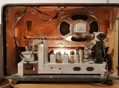
- Number of Tubes
- 8
- Main principle
- Superheterodyne (common); ZF/IF 470/10700 kHz; 2 AF stage(s)
- Tuned circuits
- 6 AM circuit(s) 10 FM circuit(s)
- Wave bands
- Broadcast, Long Wave and FM or UHF.
- Power type and voltage
- Alternating Current supply (AC) / 110; 125; 145; 220 Volt
- Loudspeaker
- Permanent Magnet Dynamic (PDyn) Loudspeaker (moving coil)
- Power out
- 5 W (unknown quality)
- from Radiomuseum.org
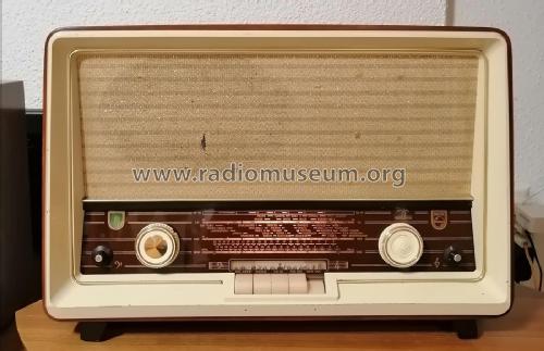
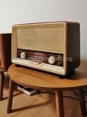
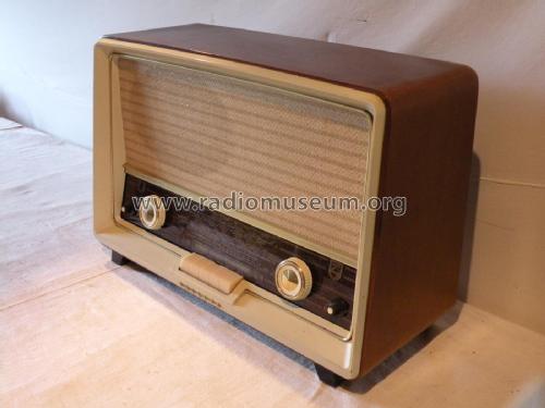
- Model: B4CH74A - Philips - Schweiz
- Shape
- Tablemodel with Push Buttons.
- Literature/Schematics (1)
- -- Schematic
- Author
- Model page created by Adrian Riesen. See "Data change" for further contributors.
- Other Models
-
Here you find 290 models, 216 with images and 224 with schematics for wireless sets etc. In French: TSF for Télégraphie sans fil.
All listed radios etc. from Philips - Schweiz
Collections
The model is part of the collections of the following members.
Forum contributions about this model: Philips - Schweiz: B4CH74A
Threads: 1 | Posts: 9
Hello Radiofriends,
I address this spectacular community asking for help:
I have a Philips radio to restore, model B4CH74A and I have a big problem. Rmorg does not have a diagram of the cord drive. My radio had no wire or pointer, so I couldn't find my way around.
If anyone has the cord replacement diagram, I would be very grateful if you could upload it here on Rmorg. I have the radio ready and it is pending for this reason. I've done several tests, but something always goes wrong. The difficulty lies in the variable capacitors being moved at the same time during channel scanning. and it is curious that the AM/FM exchange is done by switching.
My thanks in advance, from Portugal, Júlio Branco
Júlio Branco, 14.May.25