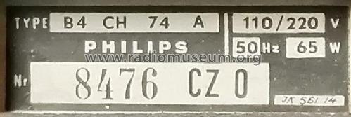
B4CH74A
Philips - Schweiz
- Hersteller / Marke
- Philips - Schweiz
- Jahr
- 1957/1958 ?
- Kategorie
- Rundfunkempfänger (Radio - oder Tuner nach WW2)
- Radiomuseum.org ID
- 313518

Sammlung Jeroen Hölscher.
Sammlung Jeroen Hölscher.
Sammlung Jeroen Hölscher.

Sammlung Jeroen Hölscher.
Sammlung Jeroen Hölscher.


Klicken Sie auf den Schaltplanausschnitt, um diesen kostenlos als Dokument anzufordern.
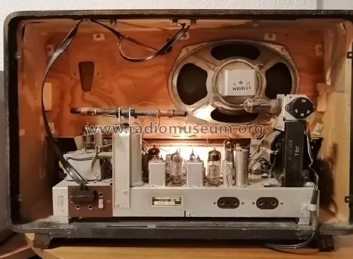
- Anzahl Röhren
- 8
- Hauptprinzip
- Superhet allgemein; ZF/IF 470/10700 kHz; 2 NF-Stufe(n)
- Anzahl Kreise
- 6 Kreis(e) AM 10 Kreis(e) FM
- Wellenbereiche
- Langwelle, Mittelwelle und UKW (FM).
- Betriebsart / Volt
- Wechselstromspeisung / 110; 125; 145; 220 Volt
- Lautsprecher
- Dynamischer LS, keine Erregerspule (permanentdynamisch)
- Belastbarkeit / Leistung
- 5 W (Qualität unbekannt)
- von Radiomuseum.org
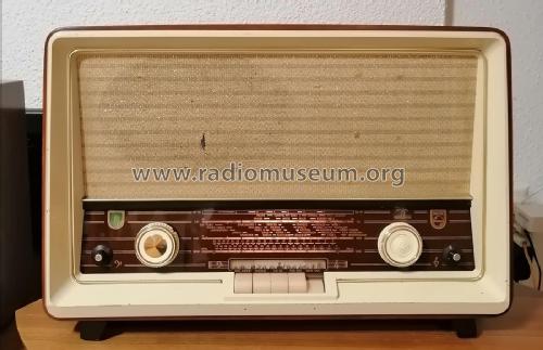
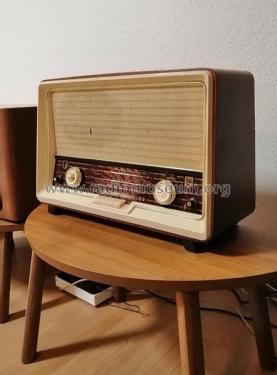
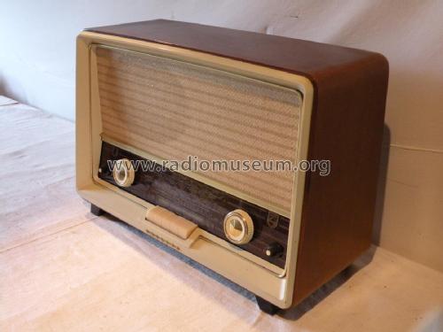
- Modell: B4CH74A - Philips - Schweiz
- Form
- Tischgerät, Tasten oder Druckknöpfe.
- Literatur/Schema (1)
- -- Schematic
- Autor
- Modellseite von Adrian Riesen angelegt. Siehe bei "Änderungsvorschlag" für weitere Mitarbeit.
- Weitere Modelle
-
Hier finden Sie 290 Modelle, davon 216 mit Bildern und 224 mit Schaltbildern.
Alle gelisteten Radios usw. von Philips - Schweiz
Sammlungen
Das Modell befindet sich in den Sammlungen folgender Mitglieder.
Forumsbeiträge zum Modell: Philips - Schweiz: B4CH74A
Threads: 1 | Posts: 9
Hello Radiofriends,
I address this spectacular community asking for help:
I have a Philips radio to restore, model B4CH74A and I have a big problem. Rmorg does not have a diagram of the cord drive. My radio had no wire or pointer, so I couldn't find my way around.
If anyone has the cord replacement diagram, I would be very grateful if you could upload it here on Rmorg. I have the radio ready and it is pending for this reason. I've done several tests, but something always goes wrong. The difficulty lies in the variable capacitors being moved at the same time during channel scanning. and it is curious that the AM/FM exchange is done by switching.
My thanks in advance, from Portugal, Júlio Branco
Júlio Branco, 14.May.25