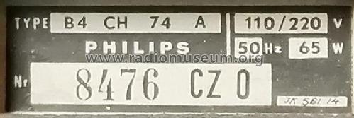
B4CH74A
Philips - Schweiz
- Pays
- Suisse
- Fabricant / Marque
- Philips - Schweiz
- Année
- 1957/1958 ?
- Catégorie
- Radio - ou tuner d'après la guerre 1939-45
- Radiomuseum.org ID
- 313518

Sammlung Jeroen Hölscher.
Sammlung Jeroen Hölscher.
Sammlung Jeroen Hölscher.

Sammlung Jeroen Hölscher.
Sammlung Jeroen Hölscher.


Cliquez sur la vignette du schéma pour le demander en tant que document gratuit.
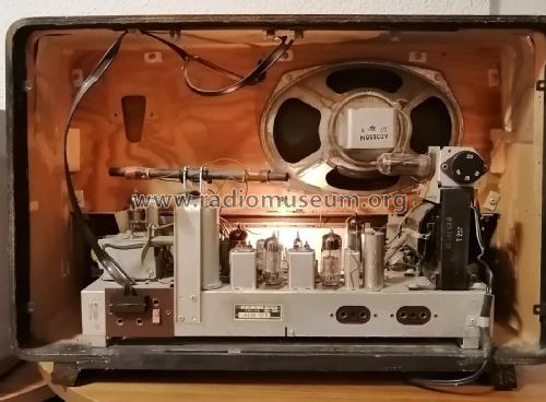
- No. de tubes
- 8
- Principe général
- Super hétérodyne (en général); FI/IF 470/10700 kHz; 2 Etage(s) BF
- Circuits accordés
- 6 Circuits MA (AM) 10 Circuits MF (FM)
- Gammes d'ondes
- PO, GO et FM
- Tension / type courant
- Alimentation Courant Alternatif (CA) / 110; 125; 145; 220 Volt
- Haut-parleur
- HP dynamique à aimant permanent + bobine mobile
- Puissance de sortie
- 5 W (qualité inconnue)
- De Radiomuseum.org
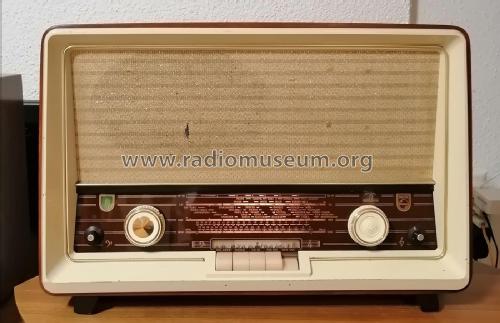
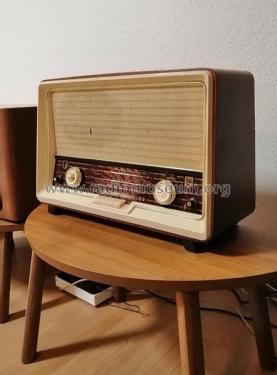
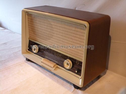
- Modèle: B4CH74A - Philips - Schweiz
- Forme
- Modèle de table avec boutons poussoirs.
- Schémathèque (1)
- -- Schematic
- Auteur
- Modèle crée par Adrian Riesen. Voir les propositions de modification pour les contributeurs supplémentaires.
- D'autres Modèles
-
Vous pourrez trouver sous ce lien 290 modèles d'appareils, 216 avec des images et 224 avec des schémas.
Tous les appareils de Philips - Schweiz
Collections
Le modèle fait partie des collections des membres suivants.
Contributions du forum pour ce modèle: Philips - Schweiz: B4CH74A
Discussions: 1 | Publications: 4
Hello Radiofriends,
I address this spectacular community asking for help:
I have a Philips radio to restore, model B4CH74A and I have a big problem. Rmorg does not have a diagram of the cord drive. My radio had no wire or pointer, so I couldn't find my way around.
If anyone has the cord replacement diagram, I would be very grateful if you could upload it here on Rmorg. I have the radio ready and it is pending for this reason. I've done several tests, but something always goes wrong. The difficulty lies in the variable capacitors being moved at the same time during channel scanning. and it is curious that the AM/FM exchange is done by switching.
My thanks in advance, from Portugal, Júlio Branco
Júlio Branco, 14.May.25