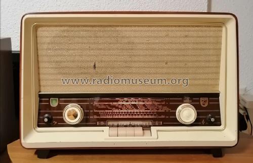
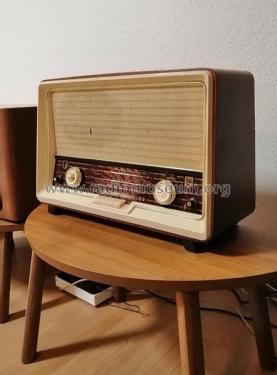
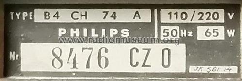
B4CH74A
Philips - Schweiz
- Paese
- Svizzera
- Produttore / Marca
- Philips - Schweiz
- Anno
- 1957/1958 ?
- Categoria
- Radio (o sintonizzatore del dopoguerra WW2)
- Radiomuseum.org ID
- 313518

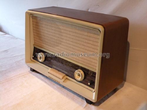
Sammlung Jeroen Hölscher.
Sammlung Jeroen Hölscher.
Sammlung Jeroen Hölscher.

Sammlung Jeroen Hölscher.
Sammlung Jeroen Hölscher.


Clicca sulla miniatura dello schema per richiederlo come documento gratuito.
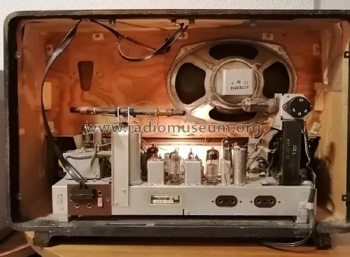
- Numero di tubi
- 8
- Principio generale
- Supereterodina (in generale); ZF/IF 470/10700 kHz; 2 Stadi BF
- N. di circuiti accordati
- 6 Circuiti Mod. Amp. (AM) 10 Circuiti Mod. Freq. (FM)
- Gamme d'onda
- Onde medie (OM), lunghe (OL) e MF (FM).
- Tensioni di funzionamento
- Alimentazione a corrente alternata (CA) / 110; 125; 145; 220 Volt
- Altoparlante
- AP magnetodinamico (magnete permanente e bobina mobile)
- Potenza d'uscita
- 5 W (qualità ignota)
- Radiomuseum.org
- Modello: B4CH74A - Philips - Schweiz
- Forma
- Soprammobile con pulsantiera/tastiera.
- Letteratura / Schemi (1)
- -- Schematic
- Autore
- Modello inviato da Adrian Riesen. Utilizzare "Proponi modifica" per inviare ulteriori dati.
- Altri modelli
-
In questo link sono elencati 290 modelli, di cui 216 con immagini e 224 con schemi.
Elenco delle radio e altri apparecchi della Philips - Schweiz
Collezioni
Il modello fa parte delle collezioni dei seguenti membri.
Discussioni nel forum su questo modello: Philips - Schweiz: B4CH74A
Argomenti: 1 | Articoli: 9
Hello Radiofriends,
I address this spectacular community asking for help:
I have a Philips radio to restore, model B4CH74A and I have a big problem. Rmorg does not have a diagram of the cord drive. My radio had no wire or pointer, so I couldn't find my way around.
If anyone has the cord replacement diagram, I would be very grateful if you could upload it here on Rmorg. I have the radio ready and it is pending for this reason. I've done several tests, but something always goes wrong. The difficulty lies in the variable capacitors being moved at the same time during channel scanning. and it is curious that the AM/FM exchange is done by switching.
My thanks in advance, from Portugal, Júlio Branco
Júlio Branco, 14.May.25