- País
- Holanda
- Fabricante / Marca
- Philips; Eindhoven (tubes international!); Miniwatt
- Año
- 1931/1932
- Categoría
- Radio - o Sintonizador pasado WW2
- Radiomuseum.org ID
- 7408

Der Stoff ist wahrscheinlich nicht original.
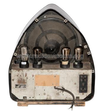
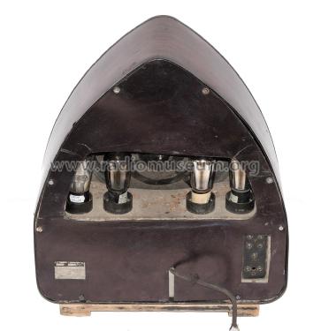


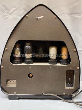


930A Rueckwand.jpg

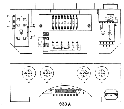
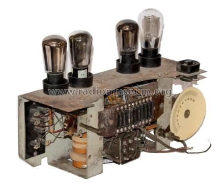
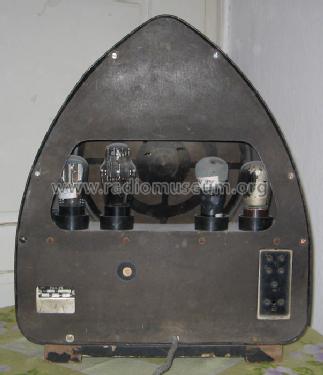
930A Innenansicht.jpg

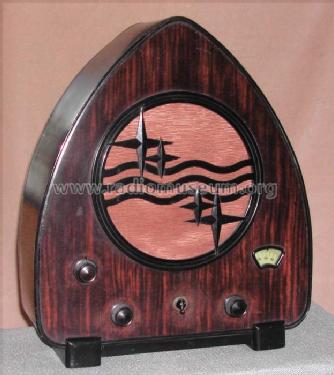
D Philips 1931 930A.jpg
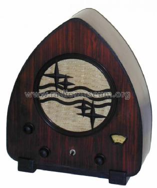
Philips Type 930A
Philips Type 930A

aus ebay, Verkäufer rosexxl
aus ebay, Verkäufer rosexxl
aus ebay, Verkäufer rosexxl

Haga clic en la miniatura esquemática para solicitarlo como documento gratuito.
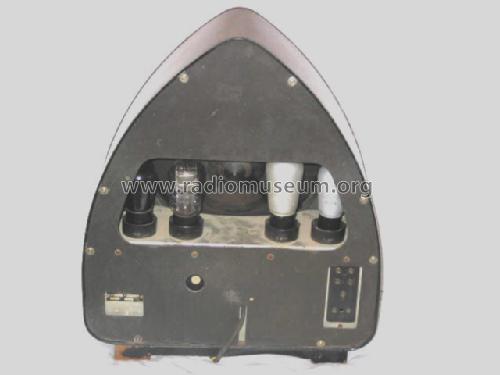
- Numero de valvulas
- 4
- Principio principal
- RFS con reacción (regenerativo); 2 Etapas de AF
- Número de circuitos sintonía
- 1 Circuíto(s) AM
- Gama de ondas
- OM y OL
- Tensión de funcionamiento
- Red: Corriente alterna (CA, Inglés = AC) / 40-100 Hz, 103; 111; 118; 127; 135; 143; 155; 196; 210; 225; 240; 253 Volt
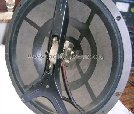
- Altavoz
- Altavoz magnético con imán de 4 polos.
- Material
- Material especial, que se describe en las notas.
- de Radiomuseum.org
- Modelo: 930A - Philips; Eindhoven tubes
- Forma
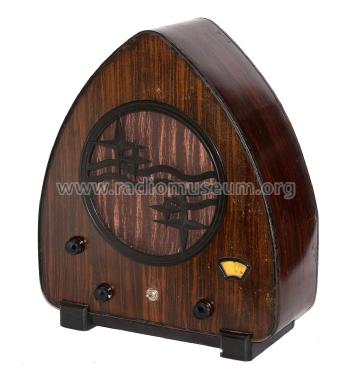
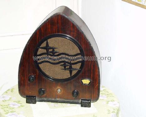
- Sobremesa tipo Capilla (upright, round top or pinted arch, not rounded edges only).
- Ancho, altura, profundidad
- 410 x 470 x 170 mm / 16.1 x 18.5 x 6.7 inch
- Anotaciones
-
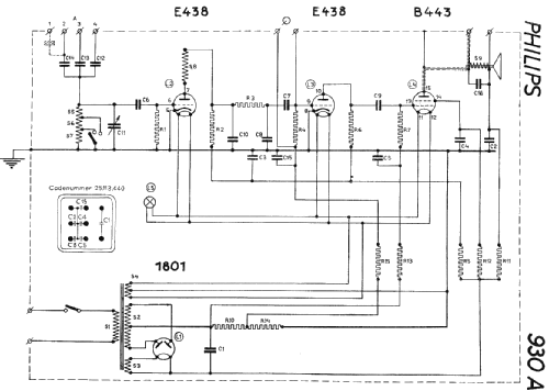
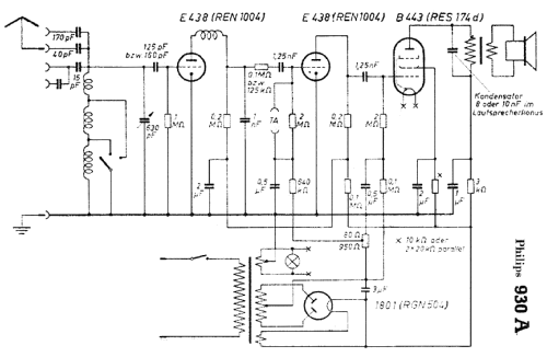
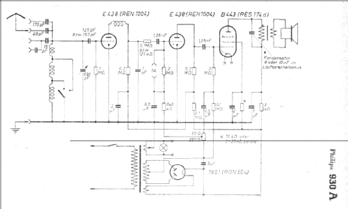
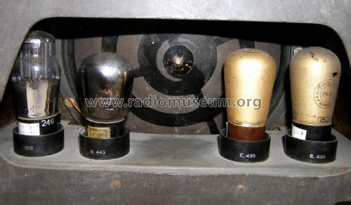
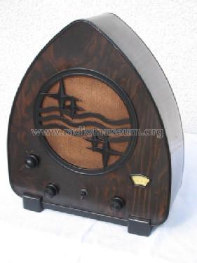
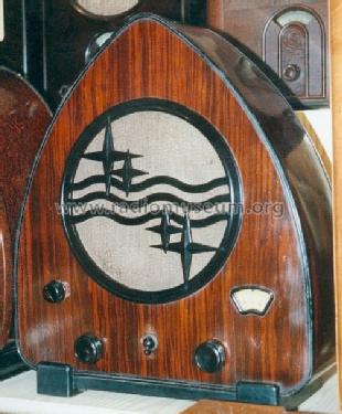
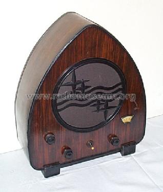
The Philips model 930A (nicknamed "Schinken" or "boîte à jambon", ham box) is a regenerative TRF, which is not quite clearly shown on the schematic - see this article.
It has three wavebands, 200 - 450 m (I), 400 - 950 m (II), and 900 - 2100 m (III).
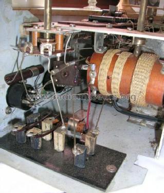
Two different mains transformers with different dimensions were used during production of the set. They are interchangeable. There are also two different variable condensers used: a mica type, and a "Lilliput" type (from February 1932 onwards).
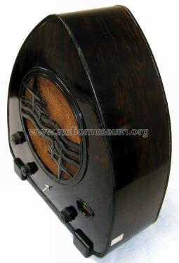
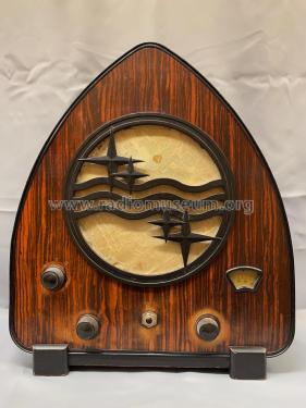
The cabinet of the 930A is made of "Arbolite" - a formica-like material made from layers of paper, cellulose and phenol resin, fused under high pressure, and finished with wood imitation print. A bakelite Philips logo covers the loudspeaker opening.
- Peso neto
- 6.8 kg / 14 lb 15.6 oz (14.978 lb)
- Procedencia de los datos
- Radiokatalog Band 1, Ernst Erb
- Referencia esquema
- Lange-Nowisch
- Documentación / Esquemas (1)
- -- Original-techn. papers.
- Otros modelos
-
Donde encontrará 5278 modelos, 4426 con imágenes y 3461 con esquemas.
Ir al listado general de Philips; Eindhoven (tubes international!); Miniwatt
Colecciones
El modelo es parte de las colecciones de los siguientes miembros.
- Matteo Agustoni (CH)
- Firmino Alves (P)
- Bernhard Beier (A)
- Peter Breu (D)
- Marc Couque (F)
- Emile Duclos (F)
- Ernst Erb (CH)
- Roberto Gabba (I)
- Spartaco Gori (I)
- Philippe Hébert (F)
- Carlos Insa Gracia (E)
- Volker Jeschkeit (I)
- John Koster (NL)
- Marc Lasnier (NL)
- Francisco Martins (P)
- Jos Mulder (NL)
- Zlatan Mumlek (HR)
- Giovanni Mura (I)
- Popescu Nicolae (RO)
- Timo Rantasaari (FIN)
- Ignacio Rodriguez-Rodriguez (E)
- Bernhard Sacherer (A)
- Karlheinz Schneider † 28.6.23 (D)
- Marcin Seliwiak (PL)
- Gil Silva (P)
- Alois Steiner (A)
- Pius Steiner (CH)
- Jörgen Svensson (S)
- Danko Tkalec (HR)
- Theodorus † Van Ginkel (E)
- Philippe Viard (F)
- Hans Vogelaar (NL)
- Albert Vonarburg (CH)
- Herbert Weilinger (A)
- Wolfgang Winkler (D)
Museos
El modelo se puede ver en los siguientes museos.
Contribuciones en el Foro acerca de este modelo: Philips; Eindhoven: 930A
Hilos: 5 | Mensajes: 21
Der 930A ist arm an eigenspezifischen Erkennungszeichen. Bei meinem 930A mit "F" ist auf dem Boden der Innenseite aller vier Kunsstoffbecher, auf welchen außen die Röhrentype vorgegeben wird, das im Bild dargestellte Logo in einer Art Schirm oder Pilz mit abgeknicktem Stiel zu sehen. Originalgröße ca. 3 mm. Ich meine, das Zeichen schon anderweitig gesehen zu haben, vermag es aber im Moment nicht zu klären. Kann jemand Hinweise geben?
Anexos
- F_Philips_930A-LogoNN-1a (116 KB)
Manfred Rathgeb, 24.Mar.20
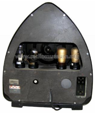
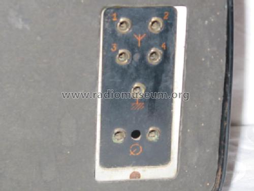
Gemeint ist der weitere Anschluß (wohl Pick-Up), den manche der unter den verschiedenen Ländern angelegten 930A zwischen dem Spannungswähler und der Platte für Antenne/Erde haben, und zwar als Aussparung im Blech und in der Rückwand. Abgebildet sind auch Geräte mit einem Loch in der Rückwand, aber ohne Pick-Up. Die meisten Geräte haben im Chassis keine zusätzliche Öffnung. Ein Karton zum Ausschneiden der Öffnungen auf der Rückwand war schon im "Handel".
Manfred Rathgeb, 12.Mar.20
Nein, nicht beim Gerät selbst, auf welches man allerdings nicht einmal eine Vase mit einem bunten Strauß oder einen Rahmen mit dem Bild der Lieben stellen kann. Kunterbunt sind die Typenschilder und bestimmt auch die Zuordnung der Sammlungsobjekte zu den einzelnen Ländern, wie unser Philips-Sachverständiger GV bei seiner unter dem 4.6.2015 gemachten Ablehnung, auch für Frankreich eine Modellseite anzulegen, befürchtete. Die von ihm und Herrn Erb in den Forumsbeiträgen zum Philips Mignon AG2100-D75 im Dezember 2019 angesprochene Systematik für Philips-Neuvorschläge sollte doch auch wenigstens für besondere und zudem vielfach angelegte Radios eingeführt werden, weil gerade bei diesen die Qualität der Anlegung gegenüber den vielen sonstigen Präsentatoren gezeigt werden kann.
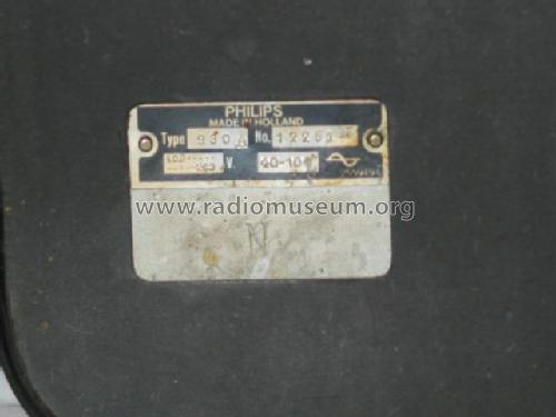
Ich habe nun die Typenschilder - soweit einigermaßen lesbar - aller bei uns angelegten und einiger weiterer Geräte erfasst, den 934A, 830A und 834A zum Vergleich, siehe meine Bilder. In der ersten "Spalte" steht die ID= oder sonstige Quelle, in der zweiten Philips mit einem eventuellen Zusatz, in der dritten "Spalte" die seriell hergestellte Eigennummer des Schildes (mal oben, mal unten oder gar nicht), in der vierten die individuelle Fertigungsnummer und in der fünften (nur beim 930A) der Buchstabe, der in der Nähe des Schildes auf das Chassis eingeprägt ist.
Ginge es nur nach der Typenbezeichnung ("930A"), so dürfte er nur unter einem und nicht unter sechs Ländern angelegt werden. Es gibt hier nämlich durchweg kein Suffix.
Die Herstellerbezeichnung Philips ist bei allen gleich, zusätzlich steht bei einem Importe de Nederlande, bei zweien Made in Holland, bei einem ist ein D im Kreis angebracht.
Die Eigennummer des Schildes ist meist 2559735, etwas weniger P045965 ( jene mit F am Ende der Individualnummer), England einmal ohne und einmal mit P036700, jenes mit D im Kreis P048626.
Die Individualnummer beginnt mit No oder Nr und endet in der Regel mit einem Buchstaben, nämlich F, C, N, D, P und Z, wobei sich die Buchstaben als Prägung auf dem Chassis wiederholen.
Auffallend ist, daß beim 934A und den meisten 830A und 834A die Eigennummer des Schildes ebenfalls 2559735 ist. Auffallend auch die ganz aus der Reihe gehenden Daten bei dem Gerät mit dem D im Kreis. Die Betriebsspannung ist nicht stets oder nur mit einem Buchstaben geprägt.
Ich bin nun ganz und gar nicht mit dem Ergebnis meiner Arbeit zufrieden, weil ich noch immer nicht weiß, welcher der bereits angelegten Modellseiten ich meinen 930A zuordnen kann. Kunterbuntes hat zwar keine Systematik, aber schön kann es trotzdem sein.
Anexos
- Schild930A-934A (169 KB)
- Schild830A-834A (197 KB)
Manfred Rathgeb, 12.Mar.20
This Philips 930A set has one of the most beautiful cases ever made, so I decided to take a closer look at the schematic.
The schematic is one of the simplest around with an input grid-leak detector, an audio preamp triode, and an output pentode. But the inductor load at the grid leak detector made me think that some regeneration (Rückkopplung) was designed in, simply by the presence of an inductive Plate load.

This use of regeneration would fall under the category of "trade secret", so there is no need to change the classification of this radio from "TRF without reaction" to "TRF with reaction". Philips probably wanted it that way.
According to F. E. Terman's 1955 Electronic and Radio Engineering 4th edition page 427, when an inductive plate load is presented to a triode, the input conductance at the grid becomes negative below the frequency of resonance at the plate. Below resonance the impedance of the tank circuit is inductive.

This resonant frequency may be very high because the only capacitance at the plate is the self-capacitance of the load inductor and the Miller-multiplied grid-to-plate capacitance. In total, this should be under 30pF, if the inductor is not simply a high inductance choke (>1mH).
The photos that were posted under this radio did not clarify for me the value and the location of this inductor.
I wonder if an owner of this radio could tell the Forum what is the approximate value of the inductance, and what is it's position relative to the other inductances. If you own an inductance meter such as the Rhode&Schwarz BN6100, it would be great to know the the self-resonant frequency of this inductor too.
Another simple test could also show the effect of the inductor on gain: Shorting out the inductor with a short wire should lower the output volume. If using a foot-long aligator jumper, you should twist the wire tightly to avoid making a loop that might couple to the input coils.
Regards,
-Joe
Joe Sousa, 07.Jul.09
I have in my collection two different versions of this radio that puzzels me a bit. The normal case seem to be that this radio has a Bakelite/Philite-base mounted at it´s bottom. Now I have found out that one of the radios has a base entirely made of black painted wood instead.
A fellow collector in Sweden claims that this is sometimes the case and that it is original and factory made. There is of course still the possibility that this base does not belong to the radio from the beginning but has been used to repair it when the original base was damaged, however it looks like it should be there and that no fiddling has been done.
Assuming that this base would be factoryassembled original gives room for at least three different explanations:
1: Either of the two bases was used in early series production, but later abandoned due to costs or other practical reasons.
2: The normal production of Bakelite/Philite bases was for some reason interrupted - be it a shortage of material, a strike among workers or whatever - forcing ahead an alternative solution for the base manufacturing, so that they still could produce the radiomodel.
3. The different bases were used in two or more different production facilities in different countries but radios from both factories may have been sold in any country.
There must be many Philips 930 A among the members in RMorg so now to my questions:
Is there anyone else who own a model 930 A (or 930 C, for that matter) with wooden base?
Does anybody know in which countries the Philips 930 A (also 930 C) was produced? When searching for the model several countries appear in the list, but not exactly same for 930 A respectively 930 C, and this puzzles me a bit.
I try to attach pictures with the two different bases below:
Anexos
- Normal base (71 KB)
- wooden base (79 KB)
Anders Söderström, 11.Aug.08