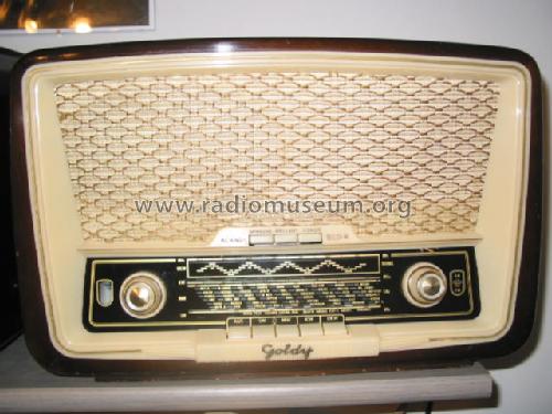
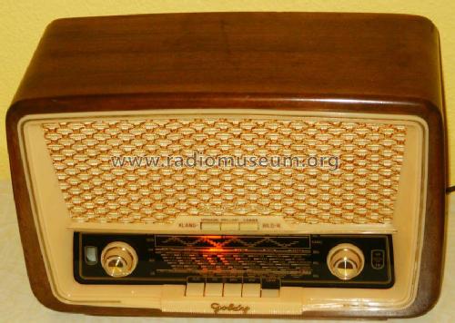
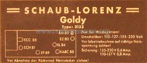
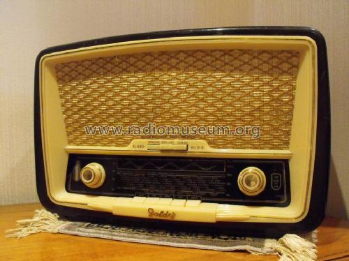
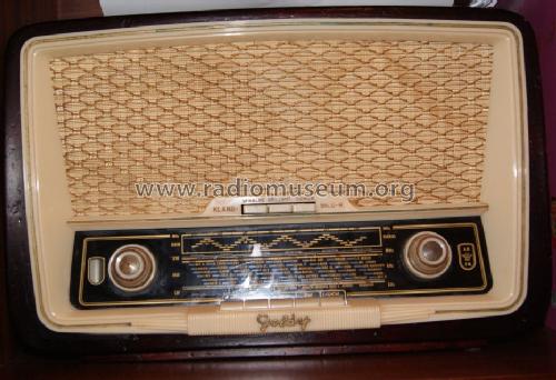
Goldy 3133
Schaub und Schaub-Lorenz
- Country
- Germany
- Manufacturer / Brand
- Schaub und Schaub-Lorenz
- Year
- 1955/1956
- Category
- Broadcast Receiver - or past WW2 Tuner
- Radiomuseum.org ID
- 20392

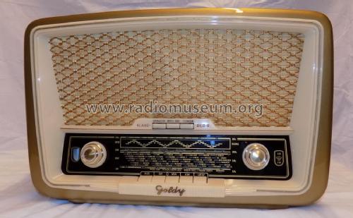

Schaub-Lorenz: Goldy 3133

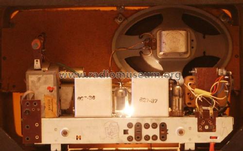
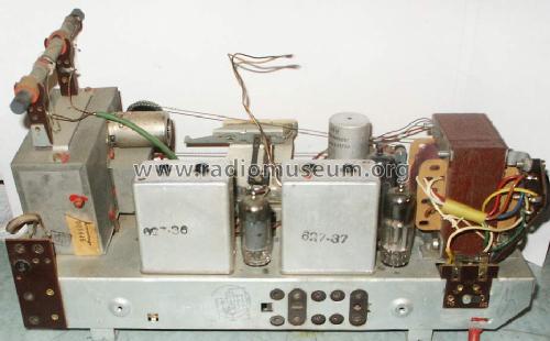
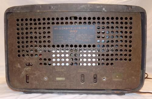
Netztrafo nicht original

S.-Nr. 409824
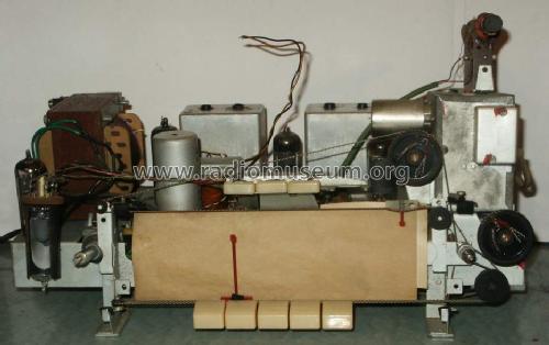
Netztrafo nicht original
Netztrafo nicht original

Netztrafo nicht original
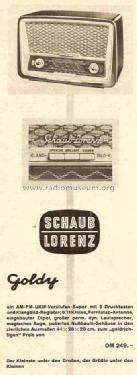
Funk-Technik 1955 / Heft 21 / Seite 603
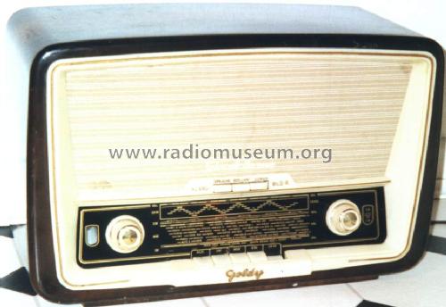
my Goldy from Shaublorenz

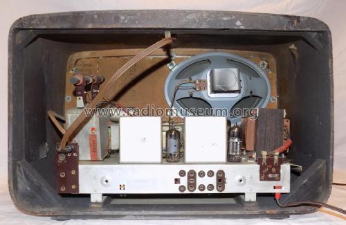
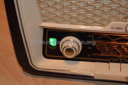
EM85 neu
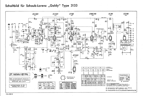
Click on the schematic thumbnail to request the schematic as a free document.
- Number of Tubes
- 7
- Main principle
- Superheterodyne (common); ZF/IF 460/10700 kHz
- Tuned circuits
- 6 AM circuit(s) 11 FM circuit(s)
- Wave bands
- Broadcast, Long Wave, Short Wave plus FM or UHF.
- Power type and voltage
- Alternating Current supply (AC) / 110; 127; 155; 220 Volt
- Loudspeaker
- Permanent Magnet Dynamic (PDyn) Loudspeaker (moving coil) - elliptical
- Material
- Wooden case
- from Radiomuseum.org
- Model: Goldy 3133 - Schaub und Schaub-Lorenz
- Shape
- Tablemodel with Push Buttons.
- Dimensions (WHD)
- 440 x 280 x 200 mm / 17.3 x 11 x 7.9 inch
- Net weight (2.2 lb = 1 kg)
- 6.4 kg / 14 lb 1.6 oz (14.097 lb)
- Price in first year of sale
- 249.00 DM
- External source of data
- Erb
- Source of data
- HdB d.Rdf-& Ferns-GrH 1955/56
- Other Models
-
Here you find 972 models, 828 with images and 689 with schematics for wireless sets etc. In French: TSF for Télégraphie sans fil.
All listed radios etc. from Schaub und Schaub-Lorenz
Collections
The model Goldy is part of the collections of the following members.
Forum contributions about this model: Schaub und Schaub-: Goldy 3133
Threads: 2 | Posts: 17
Hallo Freunde,
welchen Ersatz-Lautsprecher würdet Ihr für meinen Schaub-Lorenz Goldy 3133 empfehlen?
Ich habe leider den originalen Lautsprecher nicht mehr und kenne dessen Impedanz nicht.
Danke!
Markus
Markus Amende, 05.Mar.18
Dear Radio Friends
I've one Goldy II P (type 3620).
It's similar to 3133, so its schematic had been very useful to fix it.
The output transformer was repaired and some caps had been changed.
Now it is working.
BUT......:
It sounds loud (normal) in LW,MW, KW, but very low in UKW.
- A better aerial doesn't improve this a bit.
- ECC85 is not the problem (It was already checked).
- Also I can´t understand why its "Magic eye" tube shows better input signals in UKW than in MW, LW,KW. It might be the opposite....Don't you agree?
Do You know this models?
Do You help me? Some help would be very welcome.
Best regards
Mário
Mario Coelho, 23.Dec.04