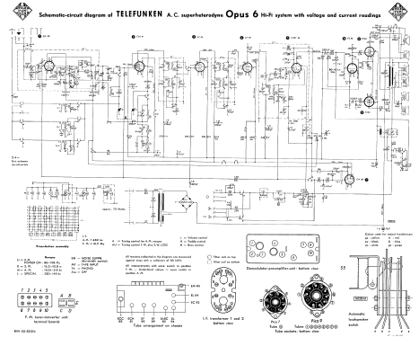
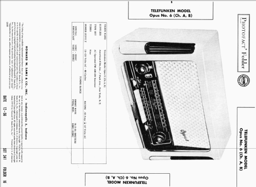
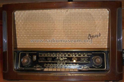
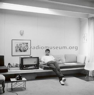
Opus 6 HiFi-System Licensed by Armstrong
Telefunken Deutschland (TFK), (Gesellschaft für drahtlose Telegraphie Telefunken mbH
- País
- Alemania
- Fabricante / Marca
- Telefunken Deutschland (TFK), (Gesellschaft für drahtlose Telegraphie Telefunken mbH
- Año
- 1955/1956
- Categoría
- Radio - o Sintonizador pasado WW2
- Radiomuseum.org ID
- 26407


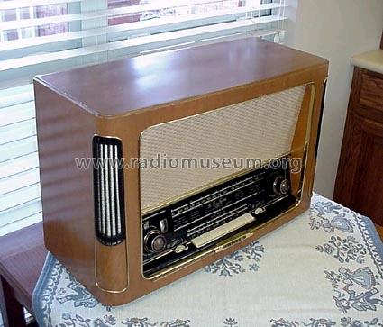
Opus 6 Exportmodell, ebay USA


Haga clic en la miniatura esquemática para solicitarlo como documento gratuito.
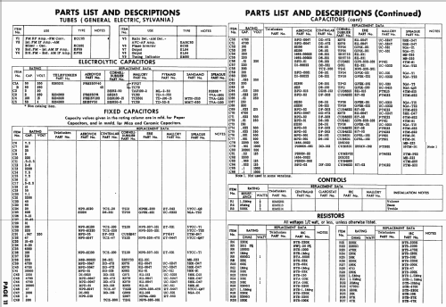
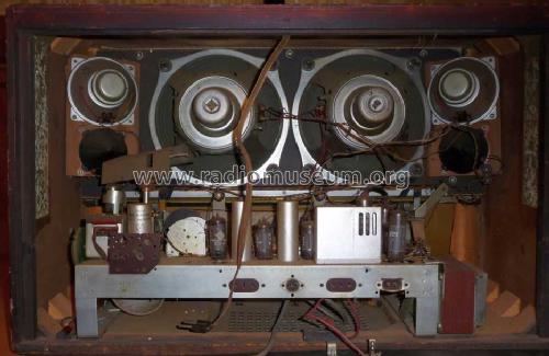
- Numero de valvulas
- 9
- Numero de transistores
- Semiconductores
- B250C125
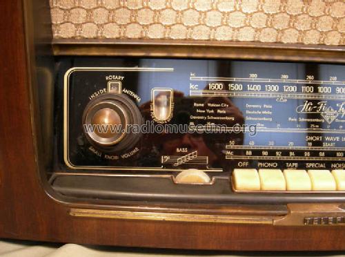
- Principio principal
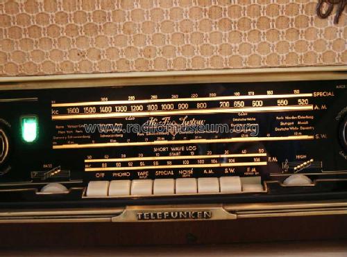
- Superheterodino en general; Modelo de Exportacion
- Número de circuitos sintonía
- 8 Circuíto(s) AM 11 Circuíto(s) FM
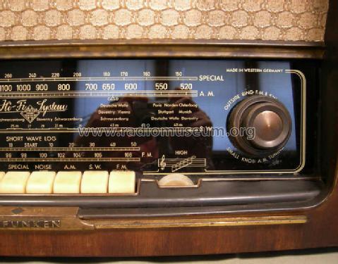
- Gama de ondas
- OM, OL, OC y FM
- Tensión de funcionamiento
- Red: Corriente alterna (CA, Inglés = AC) / 110-120 Volt
- Altavoz
- 6 Altavoces
- Potencia de salida
- 15 W (unknown quality)
- Material
- Madera
- de Radiomuseum.org
- Modelo: Opus 6 HiFi-System Licensed by Armstrong - Telefunken Deutschland TFK,
- Forma
- Sobremesa de botonera.
- Ancho, altura, profundidad
- 640 x 405 x 275 mm / 25.2 x 15.9 x 10.8 inch
- Anotaciones
- Photofact Folder, Version A and B or Chassis. Power Supply 60 Cycles. Supplier was American Elite, Inc., 7 Park Ave., New York.
- Peso neto
- 15.5 kg / 34 lb 2.3 oz (34.141 lb)
- Documentación / Esquemas (1)
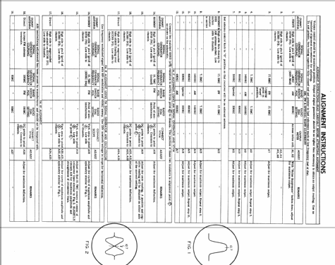
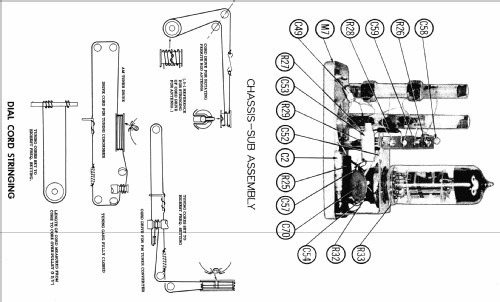
- -- Original-techn. papers.
- Otros modelos
-
Donde encontrará 3579 modelos, 3166 con imágenes y 2121 con esquemas.
Ir al listado general de Telefunken Deutschland (TFK), (Gesellschaft für drahtlose Telegraphie Telefunken mbH
Colecciones
El modelo Opus 6 es parte de las colecciones de los siguientes miembros.
Contribuciones en el Foro acerca de este modelo: Telefunken: Opus 6 HiFi-System Licensed by Armstrong
Hilos: 3 | Mensajes: 15
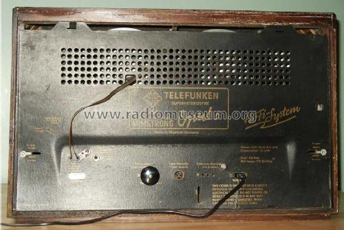
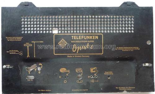
Hi, I am looking for the Telefunken Opus 6 inside back panel data information. I'd like to reproduce the one that is gone from my restoration. Any help is appreciated.
Don
Donald Husar, 18.May.21
I'm working on re-capping a Telefunken Opus 6 and I came across a Pyramid brand capacitor that isn't listed in the parts list. It appears to be a big electrolyitc capacitor 16uF - 450V that's mounted on top of the chassis by the transformer. Here's a picture the capacitor in question.
Does anyone know if this was the correct capacitor installed by the factory? I was wondering if someone may have replaced the original capacitor with the wrong size since I couldn't find this one in the parts list. Thanks!
Anexos
- Opus 6 - Pyramid cap (226 KB)
Jamie Nickel, 23.Feb.14
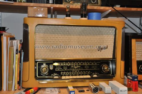
Amongst things that were done to the radio including recapping, replacement of off tolerance resistors, Ferrite antenna repair, re stringing FM, lubricating all moving parts, replacement of very weak tubes/valves, spot speaker repair on one of the speakers, the cabinet needed the base to be reattached, veneer repair, and refinishing.
Not that I'm bragging, but this is the type of stuff we are all here for!
After getting the radio to work, and adjusting the FM tuning to the scale, I wish to improve the sensitivity on MW/AM.
All connecting wires on the ferrite core antenna are connected properly and there are no shorts. All the resistors around the ECH81 are within tolerance. ECH 81 is new (Telefunken!). Radio is receiving maybe 65-75% of its potential.
How does one go about increasing the sensitivity in this radio?
Omer
P. S. This table radio, with its six speakers, is in my opinion, a Stradivarius in fiftie's German radios!
Omer Suleimanagich, 05.May.05