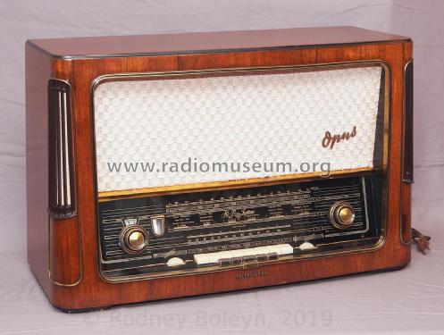
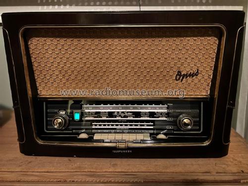
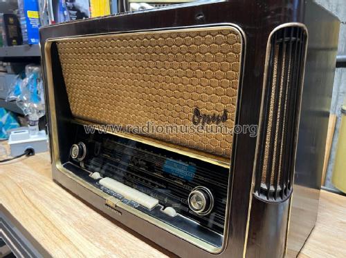
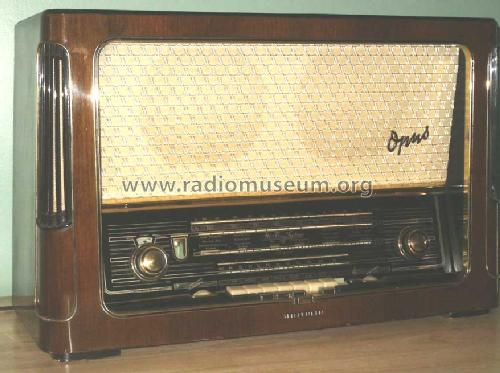
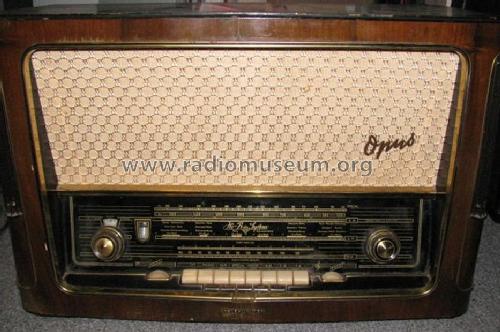
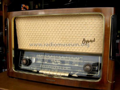
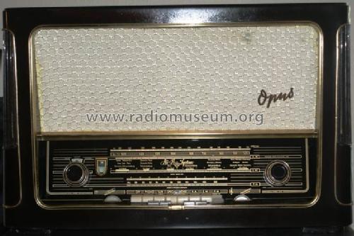
Opus 7 HiFi-System Licensed by Armstrong textile grille
Telefunken Deutschland (TFK), (Gesellschaft für drahtlose Telegraphie Telefunken mbH
- Hersteller / Marke
- Telefunken Deutschland (TFK), (Gesellschaft für drahtlose Telegraphie Telefunken mbH
- Jahr
- 1956/1957
- Kategorie
- Rundfunkempfänger (Radio - oder Tuner nach WW2)
- Radiomuseum.org ID
- 26408


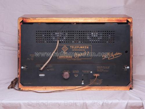
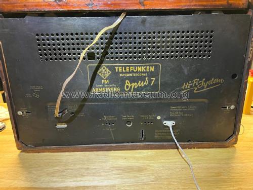
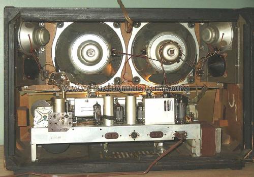
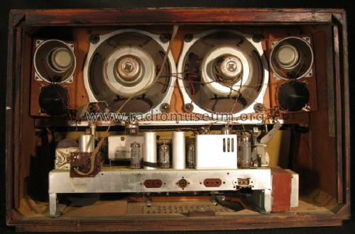
Restored view from back.

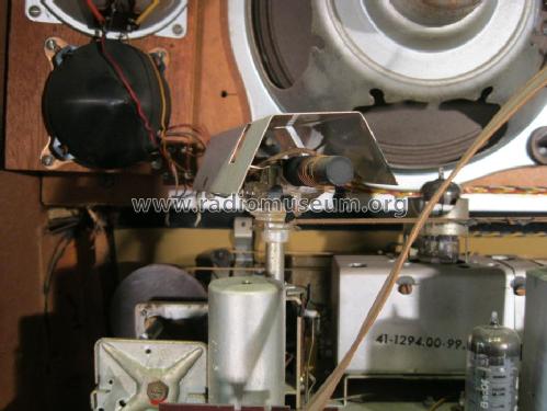
Opus 7 Antenna
Opus 7 Back Open
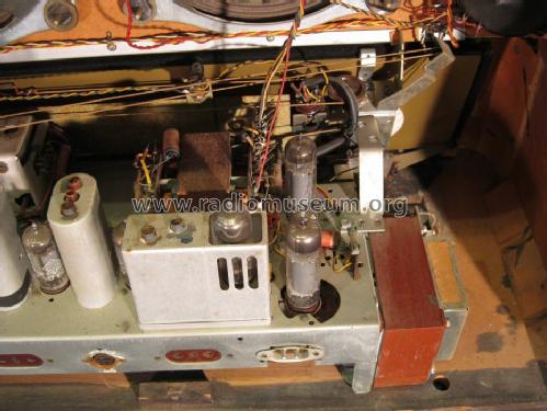
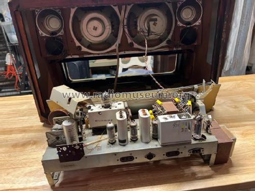
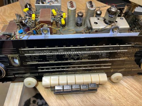
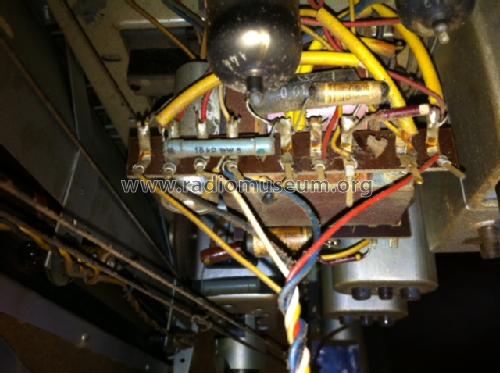
Opus 7 Chassis view #1
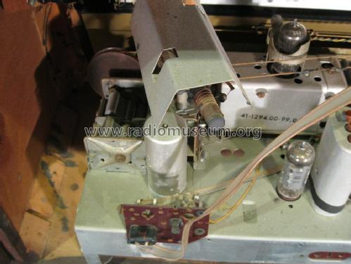
Opus 7 Chassis view #3

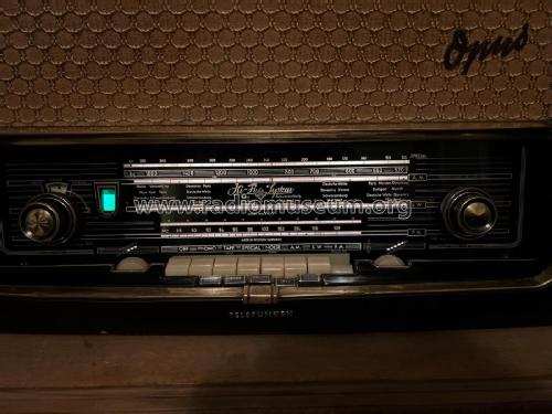
Opus 7 Front View #1
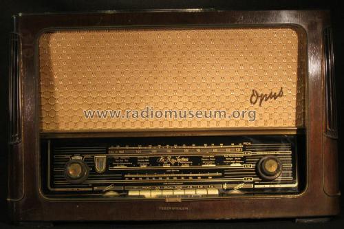
Opus 7 Front View #2
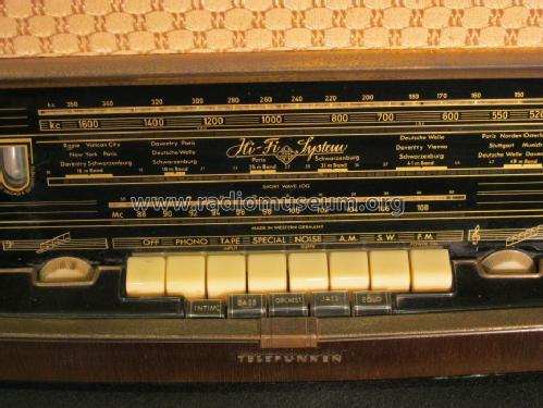
Opus 7 Front View #4

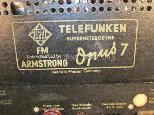
Opus 7 Inside Label
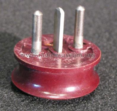
Opus 7 Front Phono Plug View #1
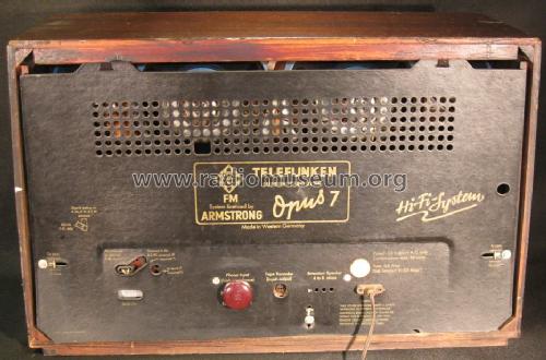
Opus 7 Rear View #1
Opus 7 Rear View #3

Opus 7 Speakers

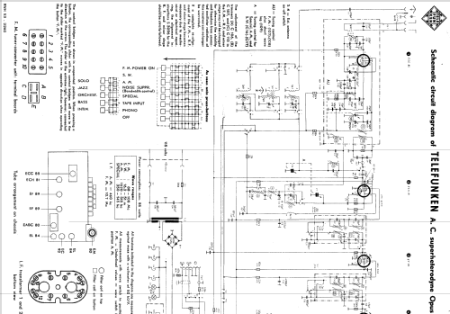
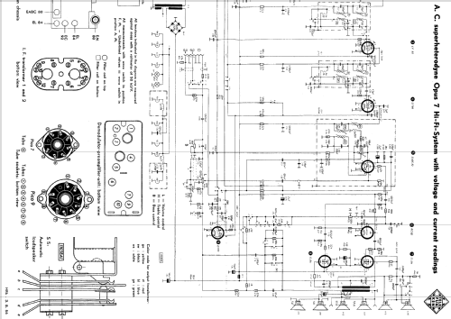
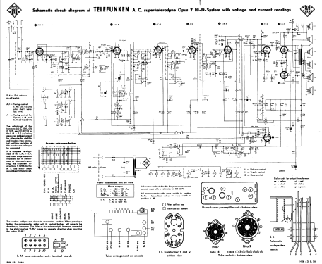
Klicken Sie auf den Schaltplanausschnitt, um diesen kostenlos als Dokument anzufordern.
- Anzahl Röhren
- 9
- Anzahl Transistoren
- Halbleiter
- B250C125
- Hauptprinzip
- Superhet allgemein; ZF/IF 460/10700 kHz; Exportmodell
- Anzahl Kreise
- 8 Kreis(e) AM 12 Kreis(e) FM
- Wellenbereiche
- Langwelle, Mittelwelle, Kurzwelle und UKW.
- Betriebsart / Volt
- Wechselstromspeisung / 110-120 Volt
- Lautsprecher
- 6 Lautsprecher
- Belastbarkeit / Leistung
- 10 W (Qualität unbekannt)
- Material
- Gerät mit Holzgehäuse
- von Radiomuseum.org
- Modell: Opus 7 HiFi-System Licensed by Armstrong [textile grille] - Telefunken Deutschland TFK,
- Form
- Tischgerät, Tasten oder Druckknöpfe.
- Abmessungen (BHT)
- 660 x 415 x 280 mm / 26 x 16.3 x 11 inch
- Bemerkung
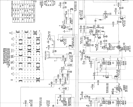
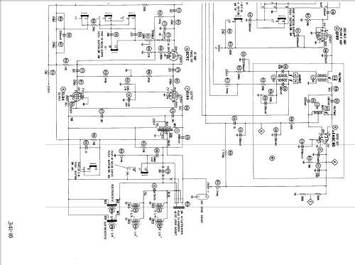
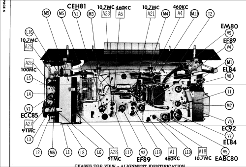
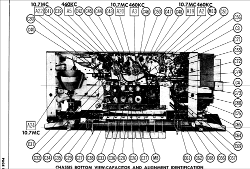
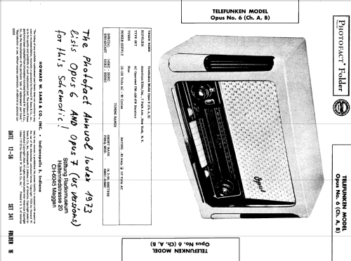
- Export model Telefunken Opus 7 is shown in the Photofact Index as being the same as export model Telefunken Opus 6 which is documented clarly in that said set 341 folder 16 from 12-56 Folder. But Opus 7 has at least the 5 additional push buttons for "Solo, Jazz, Orchester, Bass and Intim" in front of the normal 8 push buttons (both models show). There are at least Version A and B or Chassis. The Opus 7 has been made in two quite different cabinets. One has the usual textile speaker grille in front, the other has vertical wooden bars in front and ony cut outs at the sides in the woods for the other speakers. You find two different pages for them - but not different wones for the color variants which show also different glass scales and knobs.
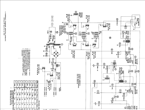
Until we can deliver schematics for the Opus 7 USA we leave the Opus 6 USA schematics according with SAMS also on model Opus 7 USA. Power Supply 60 Cycles. Supplier was American Elite, Inc., 7 Park Ave., New York.
- Nettogewicht
- 15.8 kg / 34 lb 12.8 oz (34.802 lb)
- Literatur/Schema (1)
- -- Original-techn. papers.
- Weitere Modelle
-
Hier finden Sie 3579 Modelle, davon 3166 mit Bildern und 2121 mit Schaltbildern.
Alle gelisteten Radios usw. von Telefunken Deutschland (TFK), (Gesellschaft für drahtlose Telegraphie Telefunken mbH
Sammlungen
Das Modell Opus befindet sich in den Sammlungen folgender Mitglieder.
Forumsbeiträge zum Modell: Telefunken: Opus 7 HiFi-System Licensed by Armstrong
Threads: 4 | Posts: 12
Gentlemen,
C2 an electrolytic with + to ground was not replaced. Once replace the
Tuning eye now properly responds.
I checked the cap on a new cap meter and read 2.2 uf. So that did not tell
me any thing. I hooked it up (old C2) to the simple RF gen and O-scope ESR jig and
read about 8 ohms. Now I do not know if that is acceptable for a 2 uf electrolytic but the new 2.2uf 100v cap fixed the problem.
Paul E. Pinyot † 2013, 16.Mar.10
Dennis LaCour, 21.Nov.07
When my radio is powered up the reading on my radio is 233 VDC for the B+ after the selenium bridge rectifier.
Omer
Omer Suleimanagich, 29.Dec.05
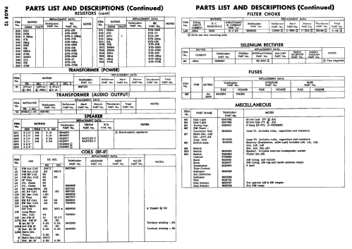
Can someone provide any information for the original power (mains) transformer for this radio.
What would be a good replacement power transformer, what is the voltage and mA for the B+, and what is the amperage rating for the filament?
Does anyone have any information for the orginal "Hannover" transfomer?
The present transformer works but is vibrating (I did tighten the four bolts to the trans).
Any sugestions on what should be done?
Kindly appreciated!
Omer
Omer Suleimanagich, 21.Nov.05