H511 Consoltone Ch= 5H01
Zenith Radio Corp.; Chicago, IL
- Country
- United States of America (USA)
- Manufacturer / Brand
- Zenith Radio Corp.; Chicago, IL
- Year
- 1951 ?
- Category
- Broadcast Receiver - or past WW2 Tuner
- Radiomuseum.org ID
- 68211
-
- alternative name: Chicago Radio Lab


Beitman
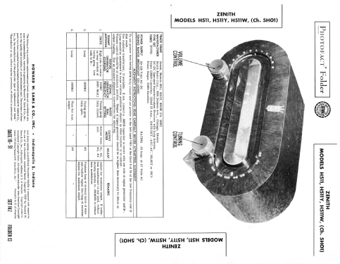
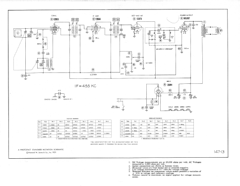


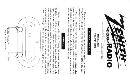

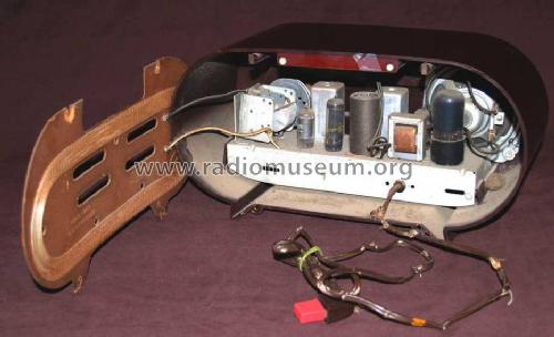
Photo by epilog57, Prague, Czech Republic
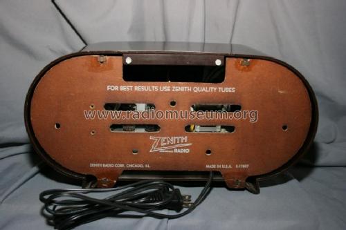
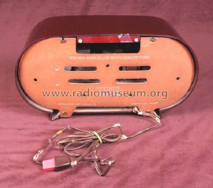
Photo by epilog57, Prague, Czech Republic

USA_Zenith_H511_brown front.jpeg
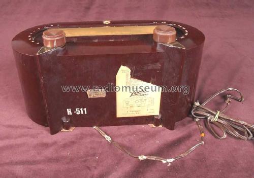
Photo by epilog57, Prague, Czech Republic
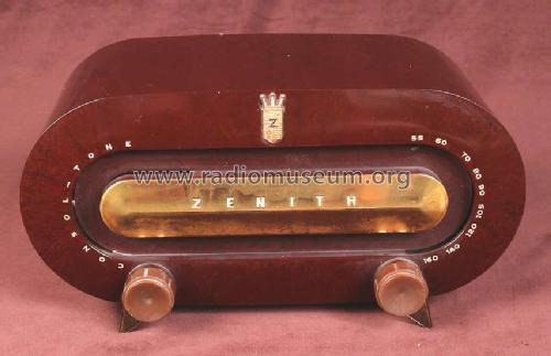
Photo by epilog57, Prague, Czech Republic
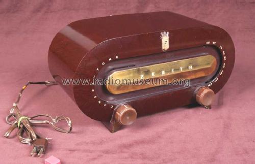
Photo by epilog57, Prague, Czech Republic

Photo by epilog57, Prague, Czech Republic
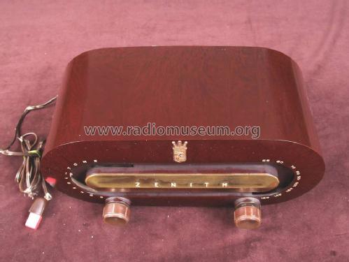
Photo by epilog57, Prague, Czech Republic


USA_Zenith_H511_front.jpeg
USA_Zenith_H511_back.jpeg
USA_Zenith_H511_brown front.jpeg
USA_Zenith_H511_bottom.jpeg
USA_Zenith_H511_interior.jpeg
American*Radio*Design Greg Mercurio

Zenith H-511 Front View #1
Zenith H-511 Front View #2
Zenith H-511 Label
Click on the schematic thumbnail to request the schematic as a free document.
- Number of Tubes
- 5
- Main principle
- Superheterodyne (common); ZF/IF 455 kHz; 2 AF stage(s)
- Tuned circuits
- 6 AM circuit(s)
- Wave bands
- Broadcast only (MW).
- Power type and voltage
- AC/DC-set / 117V = 110 -120 Volt
- Loudspeaker
- Permanent Magnet Dynamic (PDyn) Loudspeaker (moving coil) / Ø 10 cm = 3.9 inch
- Material
- Bakelite case
- from Radiomuseum.org
- Model: H511 Consoltone Ch= 5H01 - Zenith Radio Corp.; Chicago,
- Shape
- Tablemodel without push buttons, Mantel/Midget/Compact up to 14
- Dimensions (WHD)
- 350 x 170 x 150 mm / 13.8 x 6.7 x 5.9 inch
- Notes
-
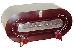
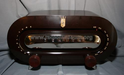
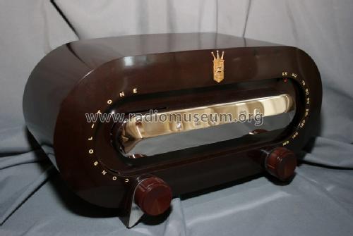
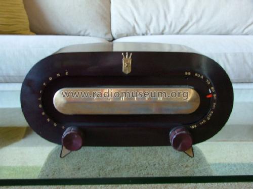
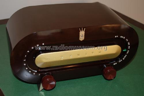
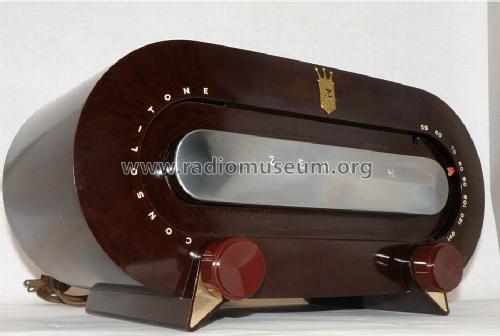
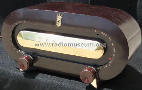
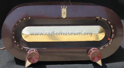
Zenith model H511 is an AC operated superheterodyne receiver with loop antenna. color: shades of brown.
- Net weight (2.2 lb = 1 kg)
- 2.3 kg / 5 lb 1.1 oz (5.066 lb)
- External source of data
- Ernst Erb
- Source of data
- The Radio Collector's Directory and Price Guide 1921 - 1965
- Circuit diagram reference
- Rider's Perpetual, Volume 22, covering 1951
- Mentioned in
- Collector's Guide to Antique Radios 4. Edition
- Literature/Schematics (1)
- Beitman Radio Diagrams, Vol. 11, 1951
- Literature/Schematics (2)
- Table Top Radios Vol. 1 Stein 98 (page 175.)
- Literature/Schematics (3)
- Photofact Folder, Howard W. SAMS (Set 147, folder 13, dated 10-51)
- Other Models
-
Here you find 4517 models, 4109 with images and 3652 with schematics for wireless sets etc. In French: TSF for Télégraphie sans fil.
All listed radios etc. from Zenith Radio Corp.; Chicago, IL
Collections
The model H511 Consoltone is part of the collections of the following members.
Forum contributions about this model: Zenith Radio Corp.;: H511 Consoltone Ch= 5H01
Threads: 4 | Posts: 13
Dear Friends:
I was preparing photos of this radio when I noticed this is a special model and not just a regular H511

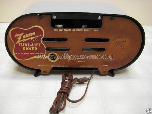
My exemplar has a "Tube Life Saver" device, which is nothing but a "slo-start" which protects the tubes from the initial current inrush. I believe this is an NTC but of course I have not opened it to take a look. The radio plays fine.

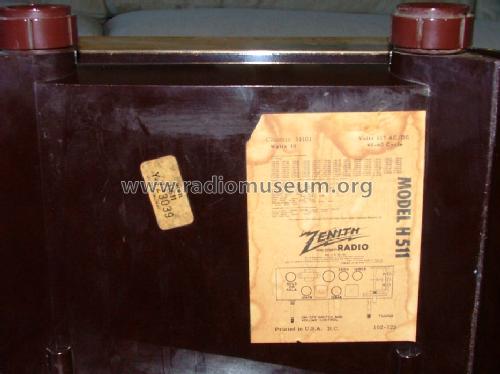
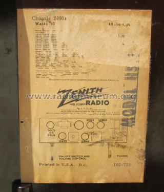
The device is placed within the filament string and it takes this radio aproximately 80 seconds to warm up and play. here is a close up on the label on the back:
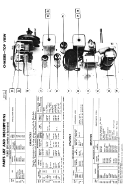
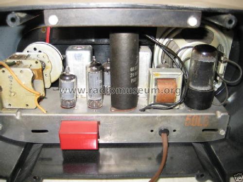
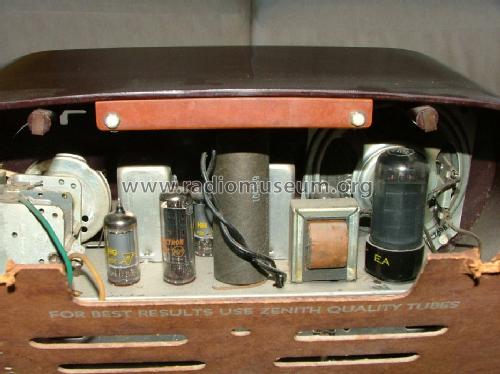
Because the device drops aprox. 6V, the tube lineup in this radio is the following: 12BE6 6BA6 12AT6 50L6GT and 35W4. This is a view of the chassis showing the device attached to the back and protected by a red metal box:
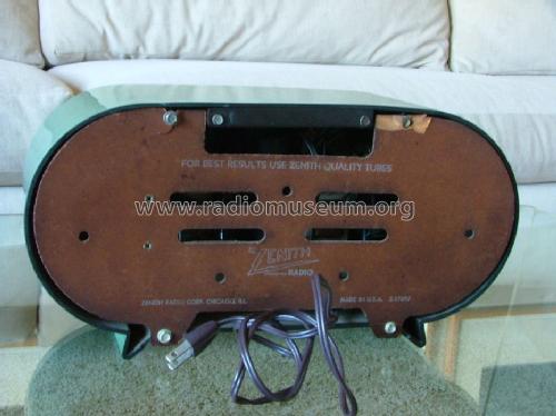
Now I am sure the chassis is 5H01 because the chassis is stamped as such:

But the question is: shall we upload this as a variant since it has a different tube lineup and a device that the other chassis don't have? None of the schematics we have show the device.
Mario
Mario Bermejo, 19.May.09
Alle Bilder können durch Anklicken vergrößert werden
1 Einführung
Kürzlich bat mich ein Kollege darum, ihm bei der Reparatur eines ZENITH H511 Consoltone (Baujahr 1951) behilflich zu sein. Das Gerät spielte auch nach mehrfachen Reparaturversuchen nur mit mäßiger Empfindlichkeit und inzwischen hatte der Eigentümer die Motivation verloren, noch mehr Zeit zu investieren. In der Tat handelt es sich beim ZENITH H511 um kein Gerät mit herausragenden Empfangseigenschaften, sondern eher um einen typischen "AA5" MW - Empfänger mit der für diesen Empfängertyp häufig eingesetzten Röhrenbestückung 12BE6, 12BA6, 12AT6, 50C5 (50L6GT) und 35W4.
Trotzdem hatte ich meine Hilfe bei der elektrischen Instandsetzung angeboten, um mich ein wenig in die Schaltungstechnik der ZENITH Geräte zu vertiefen. Auch finde ich das Gehäuse dieses Modells so ansprechend, dass es schade wäre, das Gerät im defekten Zustand als reines Dekorationsobjekt im Regal einstauben zu lassen. Da mir für die Reparaturarbeiten nur das Chassis zur Verfügung stand, hier ein Bild von der RM - Modellseite:

Abgesehen von dem hier besprochenen Modell H511 gab es eine ganze Serie von Geräten mit dem gleichen Chassis aber unterschiedlichen Gehäusefarben:
H511F Consoltone, H-511-G Consoltone, H-511-R Consoltone, H-511-W-Consoltone und H-511-Y Consoltone.
2 Schaltungsanalyse

2.1 Vorkreis
Das von der Rahmenantenne L1 aufgefangene Signal wird direkt dem g3 der als muliplikativer Mischer arbeitenden Heptode ("Pentagrid Converter) 12BE6 zugeführt. L1 und die Sektion C2 des Abstimm - Doppeldrehkos bilden den Vorkreis. Der Trimkondensator C1 dient zum Feinabgleich des Vorkreises. Ein induktiver Abgleich ist nicht vorgesehen.
Die mit R&S KARU gemessene Kapazitätsvariation des Vorkreis Abstimmdrehkos liegt bei
ΔC2 ≈ 27 ⇒ 460 pF, der Maximalwert des Paralltrimmers bei C1 ≈ 30 pF, die maximale Summenkapazität somit. bei (C1 + C2) max = 490 pF.
Untere Grenze der Empfangsfrequenz
Geht man von halb "eingedrehtem" Trimmer, also C1 = 15 pF aus, und vernachlässigt die Verdrahtungs- und Röhren- Eingangskapazität (klein gegenüber (C1 + C2)max), so erhält man (C1 + C2) = 475 pF.
Im Schaltbild erkennt man im Schriftblock links unten den für den Empfänger spezifizierten Empfangsbereich Δf Empfang = 535 ⇒ 1620 KHz
Ausgehend von einer gemessenen Kreiskapazität von 475 pF muss die Rahmenantennen zum Erreichen der unteren Bandgrenze 535 KHz eine Induktivität von L1 = 186 µH aufweisen.
Obere Grenze der Empfangsfrequenz
Die minimale Kapazität des Drehkos C2 liegt bei 27 pF. Bei wieder halb eingedrehtem Trimmer C1 =15 pF ergibt sich (C1+C2) = 42 pF und mit der oben berechneten Induktivität der Rahmenantenne von L1 = 186 µH eine obere Grenze der Empfangsfrequenz von 1800 KHz. Berücksichtigt man nun die Verdrahtungs- und Röhren- Eingangskapazität von einigen pF, so kann man davon ausgehen, dass der Drehko den spezifizierten Empfangsbereich überstreicht.
2.2 Oszillatorkreis
Der vom Oszillator überstrichene Frequienzbereich muss bekanntlich gegenüber dem Empfangsbereich Δf Empfang = 535 ⇒ 1620 KHz um die Zwischenfrequenz von 455 KHz nach oben versetzt sein, also Δf Osz = 990 ⇒ 2075 KHz.
Der Oszillatorschwingkreis wird gebildet aus der Spule L2 = 127 µH (gemessen mit R&S LARU) und der Sektion C3 des Abstimmdrehkos mit dazu parallel liegendem Trimmkondensator C1Osz. Der Kreishochpunkt wird kapazitiv (110pF) an g1 der 12BE6 gekoppelt. Die Rückkopplung erfolgt induktiv in die Kathodenzuleitung der 12BE6.
Die wieder mit R&S KARU gemessene Kapazitätsvariation des Oszillator - Drehkos liegt bei ΔC3 = 45 ⇒ 210 pF, die für den Trimmkondensator C1Osz ermittelte Maximalkapazität lag mit 20 pF etwas niedriger als beim Vorkreis.
Auf der Basis der gemessenen L- und C - Werte kann man nun die mit dem Drehkondensator erzielbare Frequenzvariation berechnen (der Trimmkondensator C1Osz wird zunächst wieder als halb eingedreht angenommen):
L2 = 127 µH, Δ(C3) +C1Osz = 55 ⇒ 220 pF ⇒ Δf Osz = 952 ⇒ 1904 KHz
Betrachtet man die höchste erfasste Empfangsfrequenz, so liegt man bei nur (1904 - 455) KHz = 1449 KHz, also weit unterhalb der geforderten 1620 KHz!.
Wiederholt man die Berechnung nun versuchsweise für vollständig deaktivierten Trimmer C1Osz, so erhält man
L2 = 127 µH, Δ(C3) = 45 ⇒ 210 pF ⇒ Δf Osz = 974 ⇒ 2105 KHz.
Das klingt zwar auf den ersten Blick vielversprechend, da der überstrichene Bereich nun schon näher am Sollbereich Δf Osz = 990 ⇒ 2075 KHz liegt, jedoch wurden bei der bisherigen Berechnung die am oberen Bandende wichtigen Schaltkapazitäten sowie die über 110 pF angekoppelte Eingangskapazität der Mischröhre 12BE6 vernachlässigt!
In der Realität wurde selbst bei vollkommen herausgedrehtem Oszillatortrimmer nur eine obere Oszillator - Frequenzgrenze von ca. 1900 KHz, entsprechend einer Empfangsfrequenz von 1445 KHz erreicht.
Mit L2 = 127 µH ergibt sich daraus ein minimale Kreiskapazität von 55 pF, also 10 pF mehr, als die minimale Kapazität des Drehkondensators ohne C1Osz. Die parasitäre Verdrahtungskapazität hat also denselben Effekt wie der halb eingedrehte Trimmkondensator.
Das bedeutet wiederum, dass es ohne Modifikation des Oszillatorkreises selbst dann nicht möglich war, den gesamten spezifierten MW - Empfangsbereich zu überstreichen, wenn man den Paralleltrimmer voll deaktivierte:
Istwert Δf empfang ≈ 500 ⇒ 1445 KHz gegenüber spezifiziertem
Sollwert Δf empfang = 535 ⇒ 1620 KHz
Diese mysteriöse Diskrepanz wird weiter unten in Abschnitt 4.3 geklärt.
2.3 ZF - Verstärker und Demodulator
Auf die Mischstufe mit der 12BE6 folgt ein einstufiger ZF -Verstärker, bestückt mit der Regelpentode 12BA6 und darauf die Demodulatorstufe mit einer 12AT6, bei der für die Demodulation beide Diodenstrecken parallel geschaltet wurden.
Die ZF - Filter sind auf 455 KHz abgestimmt, wobei das erste Filter mit der Prägung "95-1101" ein normales Bandfilter mit Parallelkondensatoren von ca. 120 pF darstellt (in der Schaltung sind die Werte nich angegeben - siehe weiter unten), während das zweite Filter (Prägung "95 1102") durch eine Besonderheit auffällt, die einem auch in anderen Zenith Radios begegnet:.
Vom Fußpunkt des Sekundärkreises werden wie üblich sowohl die Regelspannung,, als auch das NF - Signal abgenommen (grüne Leitung).
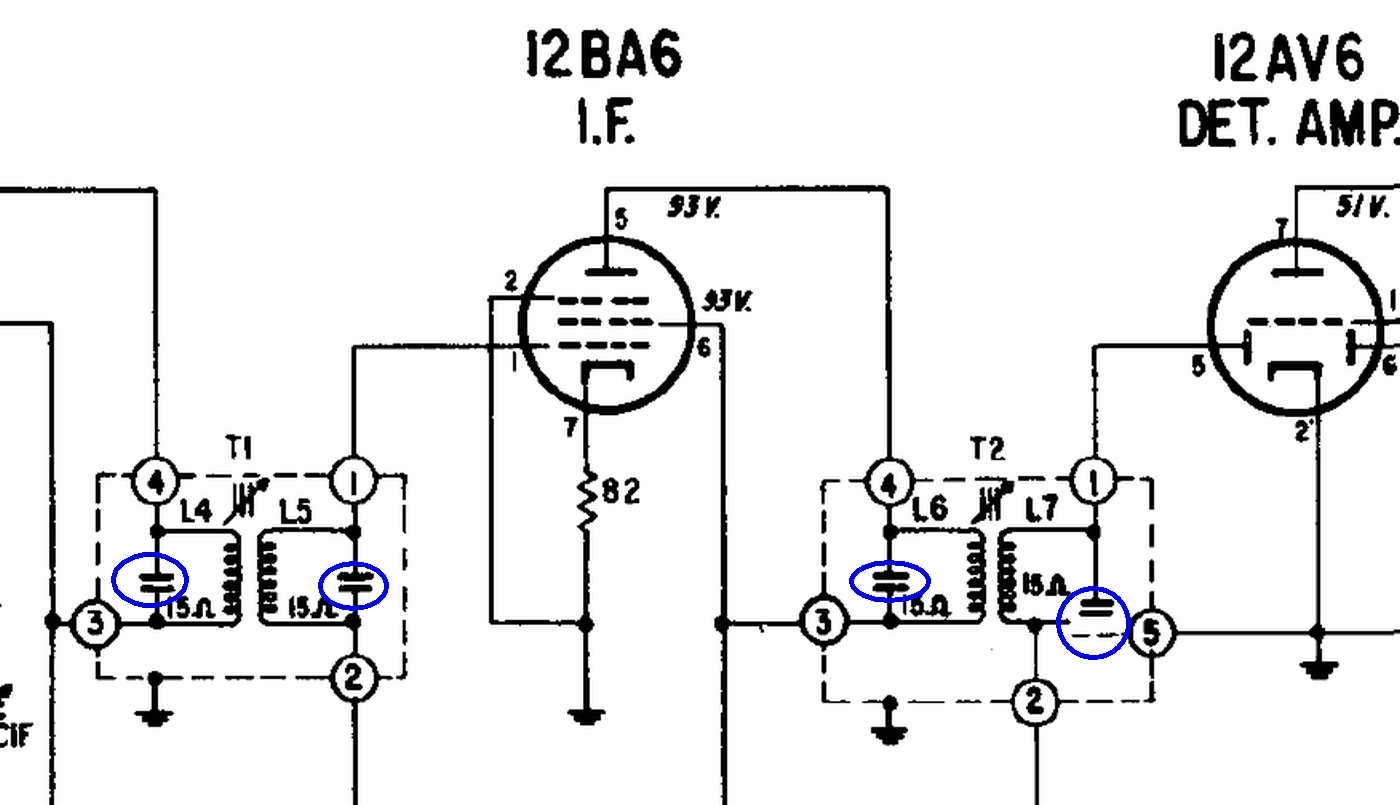
Vom diesem Fußpunkt führt ein Kondensator an die Kathode der 12AT6, liegt also parallel zum Lautstärkeregler. Im Schaltplan des H511 liegt ein zweiter Kondensator in Reihe zum Schwingkreiskondensator. Diese beiden Kondensatoren - wie auch die übrigen Bandfilterkondensatoren wurden blau eingekreist.
Hierbei handelt es sich offenbar um einen Zeichenfehler! Im Schaltbild des ZENITH G503 sieht man jedenfalls nur den wieder blau eingekreisten Kondensator ohne den beim ZENITH H511 eingezeichneten darüber liegenden Schwingkreiskondensator!
ZENITH H511 Ch=5H01 (1951) ZENITH G503 Ch=5G41 (1950)


Auch bei anderen Zenith Modellen sieht man die ungewöhnliche Kondensatorkombination am Fußpunkt des Sekundärkreises. Beim Modell 6G004Y wurden die Bandfilter zwar kapazitiv abgestimmt, aber auch hier erscheint die ungewöhnliche Fußpunktkombination.
ZENITH F615L Ch=6F05 (1962?) ZENITH 6G004Y Ch=6C41 (1947)

Wie weiter unten erläutert wird (Abschnitt 4.4), wurden die Bandfilterkondensatoren von ZENITH einfach in die Basisplatte der Filter integriert - ein Konstruktionstrick zur Senkung der Produktionskosten.
2.4 NF - Verstärker
Die NF - Vorverstärkung erfolgt im Triodensaysten der 12AT6, die Endverstärkung in der Leistungspenthode 50C5, dem Folgemodell der 50L6GT, die alternativ eingesetzt werden konnte.
2.5 Netzteil
Für die Anodenspannungsversorgung dient die Einweg - Gleichrichterröhre 35W4, zwischen deren Heizfadenanzapfung und einem Heizfadenende die Skalenlampe (6 - 8 V, 150 mA) liegt. Durch diesen Schaltungskniff wird im Einschaltmoment, also bei noch kalten Heizfäden und entsprechend hohem Heizstrom eine Überlastung der Skalenlampe ausgeschlossen.
Da die Heizfäden zusätzlich zum Heizstrom auch vom gesamten Anodenstrom durchflossen werden, glimmt die Skalenlampe anfangs nur schwach, leuchtet aber normal wenn alle Röhren ihren Betriebszustand erreicht haben.
3 Der mechanische Aufbau

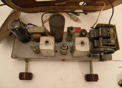
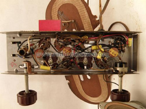
Bilder des zur Reparatur vorliegenden Gerätes


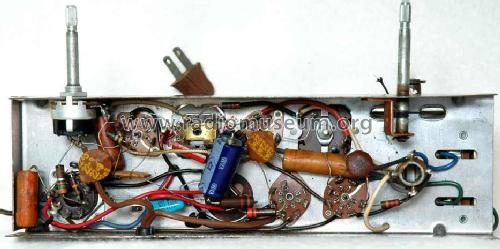
Auf der Chassisoberseite wurden keinerlei Veränderungen gegenüber dem Originalzustand vorgenommen. Lediglich der Doppel - Elektrolytkondensator 60 µF / 150 V und 20 µF/150V wurde neu befüllt.

Die Mehrzahl der Kondensatoren sowie einige Widerstände wurden erneuert.
4 Reparaturarbeiten
Der Besitzer bemängelte die schlechte Empfangsempfindlichkeit des Gerätes. Dafür waren mehrere Fehler verantwortlich, die hier beschreiben werden sollen.
4.1 Messaufbau
Im folgenden möchte ich kurz den verwendeten Messaufbau beschreiben.
- Das Messignal wurde produziert mit SMLR / 1 KHz Modulation 30 % Modulationsgrad
- Signalausgang parallel auf Frequenzzähler (Eigenbau) und Eichteiler TG-950
- Ausgang Eichteiler auf kleine Rahmenantenne (aus einem PANASONIC SA-PM17 Receiver). Spannung am Fußpunkt der Rahmenantenne ca. 2 mVss
- Die Sender - Rahmenantenne koppelt auf die Empfangs - Rahmenantenne des H511.
- Abnahme des 1 KHz NF - Signals vom Lausprecher und Anzeige auf dem Oszilloskop PM3310.
- Zur Unterdrückung des 50 Hz Brumms auf dem 1 KHz Messsignal wurde ein Hochpassfilter 2. Ordnung eingeschleift: C = 165 nF, L = 157 mH ⇒ fg ≈1KHz (Resonanzstelle).

4.2 Rahmenantenne
Der Besitzer berichtete, dass er das Gerät ohne Rückwand und damit auch ohne die darauf befestigte Rahmenantenne erstanden hatte. Er hatte daraufhin eine neue Rückwand hergestellt und diese so gestaltet, dass sie direkt mit HF - Litze bewickelt werden konnte (Im Originalzustand war die Rahmenantenne auf die Rückwand aufgeklebt).
Original Nachbildung


Beim Nachmessen stellte sich heraus, dass die Induktivität der Antennennachbildung bei 290 µH anstelle des in Abschnitt 2.1 angegebenen Sollwertes von 186 µH lag. Durch Abwickeln einiger Windungen ergaben sich 185 µH.
Der Vorkreis liess sich nun durch Justierung des Drehko - Paralleltrimmers C1 wieder korrekt abgleichen.
4.3 Oszillator
Als problematischer erwies sich das Phänomen der unzureichenden Oszillator - Frequenzvariation.
Normalerweise hat man beim Oszillatorkreis die Möglichkeit des induktiven und kapazitiven Abgleichs - im vorliegenden Fall leider nur des kapazitiven.
Da auch bei vollkommen herausgedrehtem Paralleltrimmer die durch den Drehkondensator erzielte Frequenzvariation nicht ausreichte, musste das Problem durch eine zu hohe Parallelkapazität im Oszillatorkreis verursacht werden (Am Rotor das Drehkondensators waren keine Änderungen wie z.B. verbogene Platten erkennbar).
Diese kann mehrere Gründe haben:
- Unzulässig hohe Eingangskapazität am Oszillatorgitter der 12BE6. Die im Gerät vorgefundene Röhre ist "GM Delco" gestempelt.
- Einlagerung von Feuchtigkeit in die Oszillatorspule (Wasser hat eine Dielektrizitätskonstante ε = 81 gegenüber Luft mit ε ≈ 1).
- Zeitliche Veränderung der Dielektrizitätskonstante des Vergussmittels - im vorliegenden Fall Wachs.
Zu 1.) Verwendung einer Ersatzröhre des Herstellers LORENZ brachte keine Verbesserung.
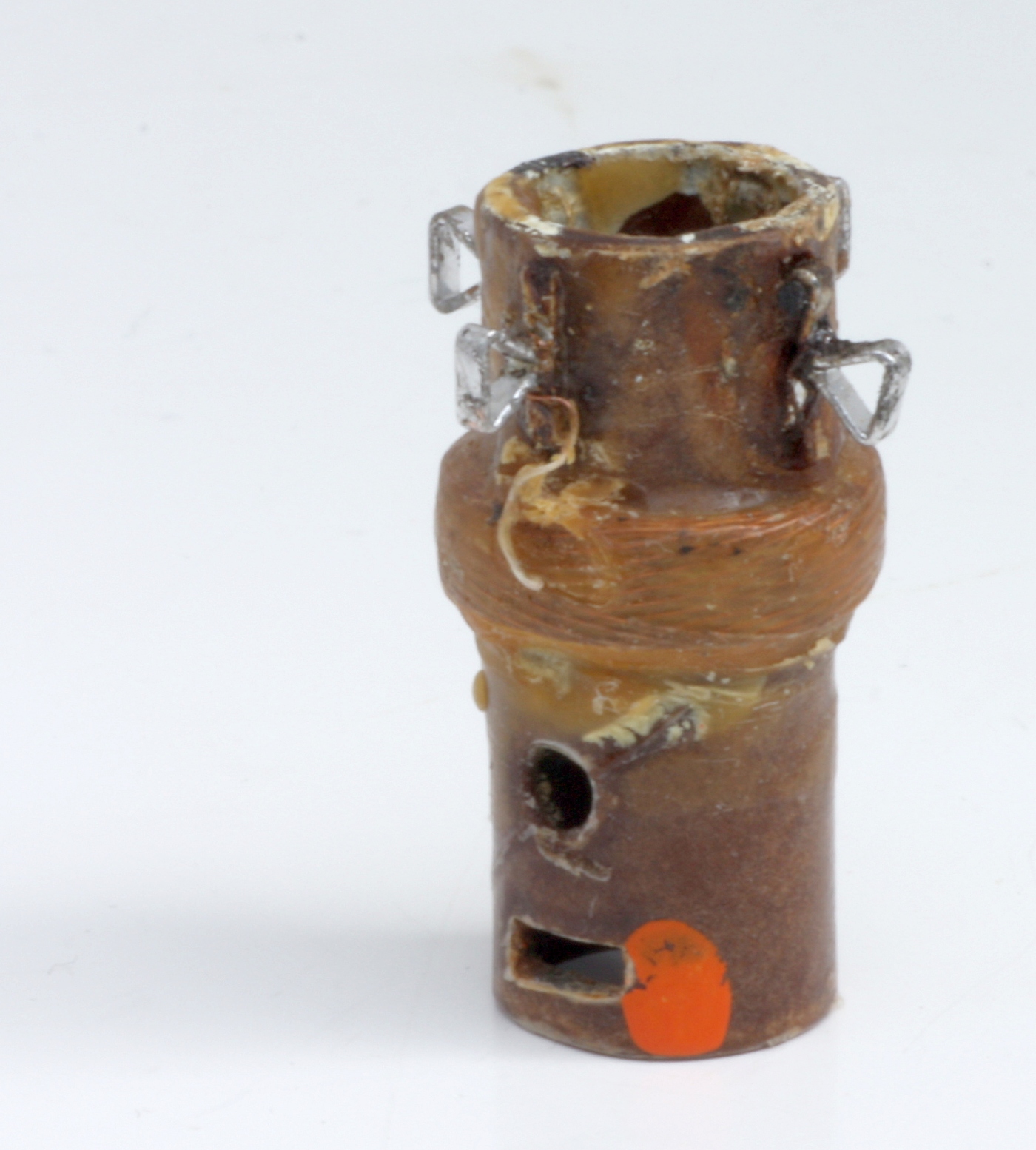
Zu 2.) Um den zweiten Fall auszuschließen, wurde die Spule ausgebaut und so weit erhitzt, bis der Wachs dünnflüssig wurde und heraustropfte. Hier 2 Bilder vom ursprüglichen und jetzigen Aussehen der Oszillatorspule:

Die Veränderung der Eigenkapazität der Spule wurde durch Messung ihrer Resonanzfrequenz (ohne äußere Beschaltung) ermittelt. Zur Messung wurde der hier beschriebene EXCITER verwendet.
Vor dem Erhitzen lag die Eigenfrequenz der Oszillatorspule bei 3,488 MHz. Mit der Induktivität der Oszillatorspule von 127 µH ergibt sich hieraus eine Paralelkapazität von 16,4 pF.
Nach Erhitzen der Spule änderte sich die Eigenfrequenz nur marginal. Ein Einfluss von eindiffundierter Feuchtigkeit konnte also ausgeschlossen werden.
zu 3.) Natürlich hätte man nun durch Immersion der Spule in ein entsprechendes Lösungsmittel den Wachsverguss total entfernen und so überprüfen können, ob sich die Dielektrizitätskonstante des Vergussmittels geändert hatte. Ich hatte aber Bedenken hinsichtlich der mechanischen Stabilität des Kreuzwickels bei fehlendem Vergussmittel. Der Punkt wurde daher nicht weiter verfolgt.
Den ausschlaggebenden Hinweis zur Lösung des Problems gab mir das RM Mitglied Hans M. Knoll, der vorschlug, die Umgebung / Beschaltung des Oszillatorkreises einer näheren Inspektion zu unterziehen.
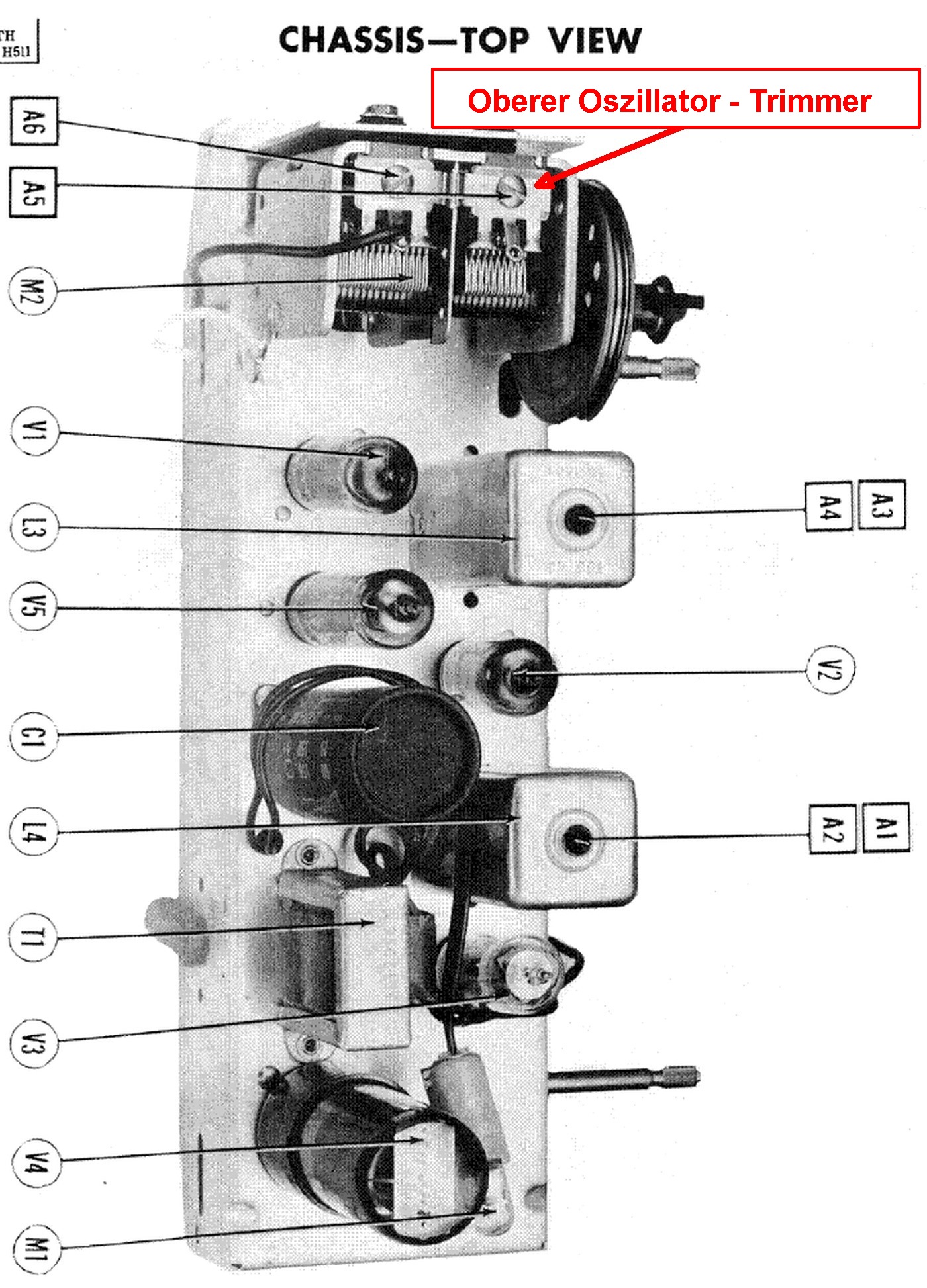
So wurde abschließend der Drehkondensator ausgebaut. Überraschenderweise zeigte sich dabei, dass nicht nur auf dessen Oberseite Trimmkondensatoren für den Feinabgleich von Vor- und Oszillatorkreis vorhanden waren, sondern dass das Oszillatorpaket auch auf der Unterseite mit einem solchen Paralleltrimmer ausgerüstet war.
Abstimmdrehko Oberseite Abstimmdrehko Unterseite


⇐ Versteckte Trimmerpostion
Bei eingebautem Drehkondensator konnte man den Kopf der Stellschraube zwar durch einen kleinen Schlitz im Chassis sehen, aber ihre Funktion nicht erkennen.
Die Kapazitätswerte des Oszillatorkreises wurden am ausgebauten Drehko mit und ohne Paralleltrimmer noch einmal gemessen und folgendes erfreuliche Resultat gefunden
- Obere Stellschraube voll gelöst, untere noch fest angezogen: Cmin = 38 pF, Cmax = 202 pF
- Obere und untere Trimmer - Stellschraube gelöst: Cmin = 11 pF, Cmax = 175 pF
Der zunächst unbeachtete untere Trimmer brachte also eine Parallelkapazität von
C1Osz, unten = 27 pF (!) in den Oszillatorkreis ein. Dies führte dazu, daß die vom Oszillatordrehko erzielte Kapazitätsvariation nicht ausreichte, um den gesamten MW - Bereich zu überstreichen.
Nach Reinigung und Erneuerung der Gummidurchführungen in der Drehkohalterung wurde der untere Trimmer auf 10 pF justiert und alles wieder eingebaut.
Die Oszillator - Frequenzvariation konnte nun problemlos mit dem oberen Paralleltrimmer so justiert werden, dass der gesamte MW - Bereich 535 - 1620 KHz überstrichen wurde.
Erstaunlicherweise wird dieser untere Oszillatortrimmer weder in den ZENITH - Serviceunterlagen erwähnt, noch taucht er in den schematischen Darstellungen auf:

Offenbar handelte es sich um eine Komponente, die bereits in der Fertigung eingestellt wurde und für die keine weitere Justage vorgesehen war. Die jetzt vorgefundene falsche Einstellung geht vermutlich auf einen mislungenen Reparaturversuch zurück.
4.4 Die ZF - Filter
Als schwierigstes Problem erwies sich die Reparatur der ZF - Filter, die durch vorherige Reparaturversuche beschädigt worden waren. Dazu hier zunächst einige Bilder des ersten ZF - Filters:


Die Spulenkörper der beiden ZF - Filter bestehen aus 0,4 mm starken, imprägnierten Papperöhrchen mit 7 mm Außendurchmesser. Zur Kernführung wurden diese mit 3 Längssicken versehen, von denen eine mit einer Kerbprägung ausgestattet wurde.
 Der Abgeich der Spulen erfolgte über 2 Hohlkerne mit Innen - Sechskantloch in Zollmaß. Da die Spulenkörper kein Gewinde trugen, verließ man sich darauf, dass die Kerne beim Hineindrehen ihr eigenes Gewinde in die Längssicken der Papperöhrchen schnitten. Zum einmaligen Fertigungsabgleich ist diese recht fiigrane Konstruktion ausreichend. Sie war aber sicher nicht zum mehrfachen Nachjustieren geeignet, da die etwas rauhe Oberfläche der Feritkerne dann zusehends die Innenseite des Papperöhrchen beschädigt und einen sauberen, reproduzierbaren Abgleich unmöglich gemacht hätte.
Zum Verstellen der Kerne wurde ein spezieller Abgleichschlüssel (gelb in nebenstehendem Bild) benötigt, der am unteren Ende eines zylindrischen "Stengels" einen etwa 10 mm langen Sechskant - Ansatz hat. Da der Durchmesser des Stengels kleiner als die Schlüsselweite des Innen - Sechskants war, konnte man mit dem Schlüssel durch den oberen Kern hindurchgreifen und nur den unteren verstellen.
War der untere Kern in der korrekten Position, zog man den Schlüssel etwas heraus, sodaß er in den oberen Kern eingriff und konnte nun diesen verstellen.
Die ganze Prozedur war notwendig, da der untere Kern nicht von der Filterunterseite zugänglich war (dort befindet sich die Befestigungsschraube der Filtereinheit).
Unglücklicherweise saßen beim vorliegenden Gerät die originalen Hohlkerne so fest im Spulenkörper, dass sie sich nicht mehr drehen ließen. So wurde beschlossen, sie zu zerstören und durch andere Kerne zu ersetzen.
Hierzu kann man einen metrischen Sechskant - Stahlschlüssel in die Kerne einführen, dessen Schlüsselweite etwas kleiner ist, als die der originalen Kerne. Dreht man den Schlüssel, so wird der spröde Ferritkern durch die Flankenbelastung gesprengt und man kann die Bruchstücke herausschütteln.
Vor dieser Aktion empfiehlt es sich, den Spulenkörper in seiner Führung durch einen stabilen Kleber zu fixieren. Dreht sich der Spulenkörper beim Zerstören der Kerne mit, so reißen leicht die sehr empfindlichen Spulendrähte ab! Zwar wird der Spulenkörper beim Zersprengen des Kerns etwas gedehnt, das stellte aber im vorliegenden Fall kein Problem dar.
Nun können in die Papperöhrchen neue Spulenkörper mit metrischen Maßen eingesetzt werden. Obwohl der Innendurchmesser der Röhrchen bei 6,2 mm liegt, kann man leider keine metrischen Spulenkörper mit 6 mm Außendurchmesser verwenden. Die oben erwähnten Kernführungssicken verjüngen den Innendurchmesser der Röhrchen so stark, dass ein 6 mm Körper nur unter Druck eingeschoben werden können. Dies birgt die Gefahr, die sehr (!) empfindlichen Papperöhrchen zu zerbrechen.
Um kein Risiko einzugehen, wurden neue Spulenkörper mit 5 mm Außendurchmesser verwendet, die es im Handel in unterschiedlichen Längen mit dazu passenden Kernen in unterschiedlichen Permeabilitätsgruppen gibt.

Kerne mit gelbem, magenta oder weißem Farbpunkt sind für die Verwendung auf MW und LW gedacht, solche mit rotem oder grünem Farbpunkt für KW.

Das nebenstehende Bild zeigt noch einmal den Aufbau des ersten ZF - Filters und daneben den neuen 5 mmØ Spulenkörper mit Kernen. Es wurden Kerne mit gelbem Farbpunkt verwendet, die, um einen Abgleich auf 455 KHz zu erreichen, nur sehr wenig in die Spulen eintauchen mussten. Auf dem Bild ist das durch die perspektivische Verzerrung nicht gut zu erkennen.
Bekanntlich werden die Kerne von der jeweiligen Außenseite in die Spulen geschraubt - es wird also ohne Kernkopplung gearbeitet!
Wichtig zu erwähnen ist die Tatsache, daß die Filter mit unterkritischer Kopplung arbeiten. So beeinflusst der Abgleich einer Spule kaum den Abgleich der anderen. Man kann also den unteren Spulenkern eindrehen und justieren und danach den oberen eindrehen und justieren, ohne dass der Abgleich des unteren Kreises gestört wird.
Im vorliegenden Fall wurde das so kontrolliert, dass nach erfolgtem unteren Kreis - Abgleich dessen Resonanzfrequenz mit Hilfe des EXCITERS gemessen wurde. Danach wurde der obere Kern bis zum Resonanzpunkt des oberen Kreises eigedreht und dabei nur eine vernachlässigbar kleine Frequenzverschiebung des unteren Kreises beobachtet.
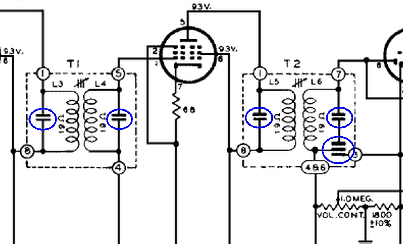 Beim Betrachten des ZF - Filter - Innenaufbaus fragt man sich, wo die im Schaltbild eingezeichneten, hier blau markierten Kreiskondensatoren liegen.
Die Antwort: Die Anschlussfahnen der Spulendrähte sind zwischen den beiden Pertinaxscheiben im Filterboden zur Spulenachse hin als kleine "Fächer" ausgebildet. Zwischen den 2 Fächern einer Spule liegt eine Glimmerscheibe. Die beiden Fächer bilden mit der dazwischen liegenden Glimmerscheibe den jeweiligen Kreiskondensator.
Spulenanschlüsse: rot und grün, Glimmerscheibe: blau

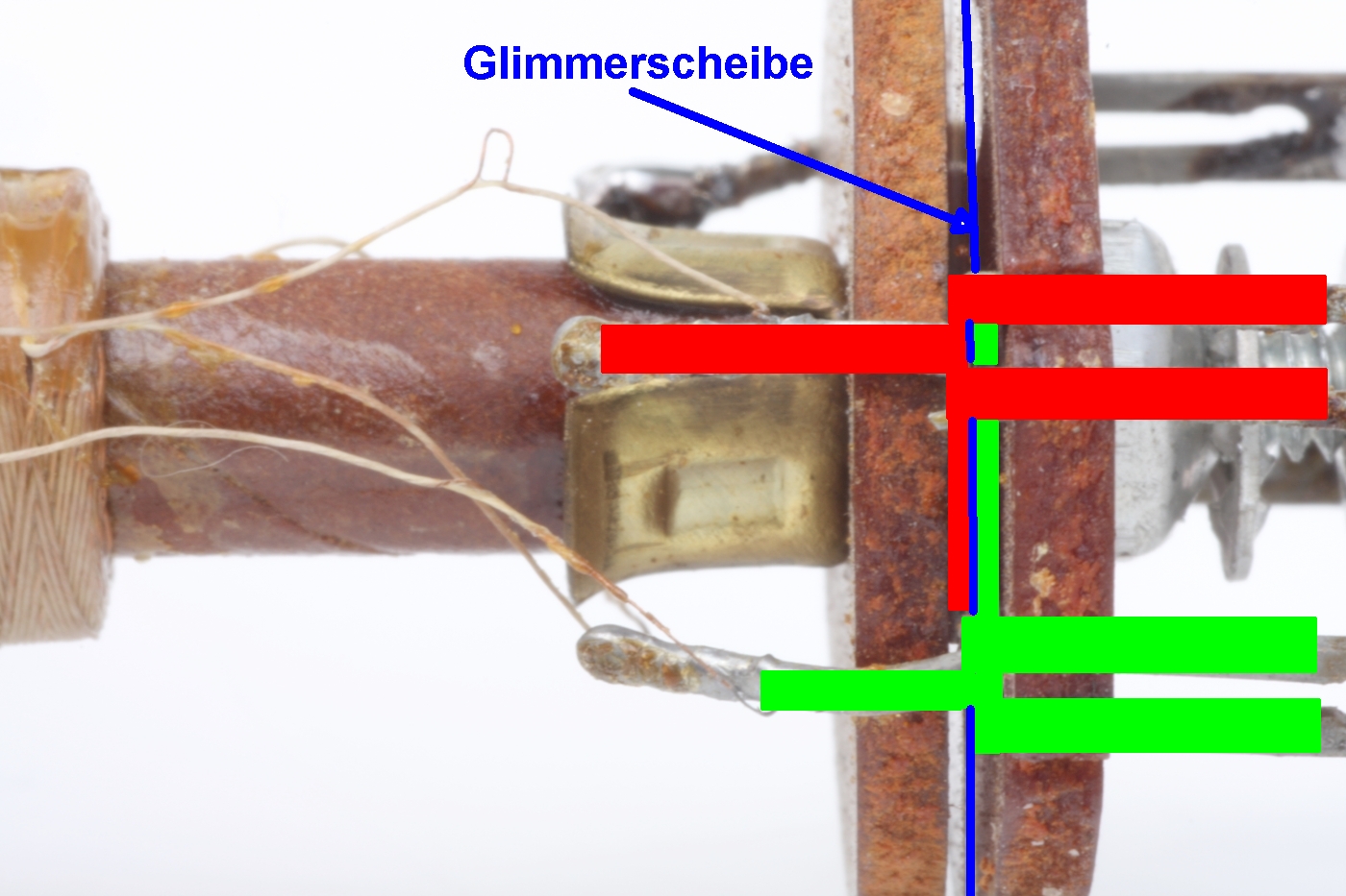
Durch diesen Trick der in den Filterboden integrierten Kondensatoren hat man sich die Kosten für externe Kondensatoren gespart.
Es lag natürlich nahe, aus kostentechnischen Gründen auch die Kondensatoren am Fußpunkt des Sekundärkreises im 2. ZF - Filter als solche Glimmerkondensatoren auszubilden.
6 Schlussbemerkung

Das Gerät funktioniert zwar nach den beschriebenen Aktionen wieder einwandfrei, jedoch lässt die Empangsempfindlichkeit wirklich etwas zu wünschen übrig.
Angesichts der Tatsache, dass das Modell H511 wie auch das kürzlich von mir beschriebene ZENITH Modell G503 Ch=5G41 von ZENITH als "Long Distance Radio" angepriesen wurde, finde ich das Ergebnis etwas enttäuschend. Aber vielleicht sollte man an die Empfangseigenschaften eines standardmäßigen "AA5" - Empfängers keine zu hohen Erwartungen knüpfen
Mein Dank geht an Hans M. Knoll für seine Unterstützung beim Aufspüren des Oszillatorfehlers.
Harald Giese
Harald Giese, 26.Apr.23
It looks like this version is an export one. BC and SW. Need for a new model or within bandwith of this one?
Attachments
- Zenith H511 front (244 KB)
- Optimized-H511 rear (121 KB)
Bart Slager, 05.Aug.16
Please click on the pics for magnification
1 Introduction
Recently a fellow radio collector asked me to give him a helping hand with the repair of his ZENITH H511 Consoltone (Vintage 1951). After several repair attempts, the reception sensitivity of the set did still not live up to his expectations, and his motivation to invest more time had dropped to zero.
As a matter of fact, one should not expect miraculous reception results from this kind of radio. The ZENITH H511 was just a standard "AA5" mediium wave receiver, using the then frequently seen tube line-up 12BE6, 12BA6, 12AT6, 50C5 (50L6GT) and 35W4.
Nevertheless I offered my help. On one hand, I was eager to learn a bit more about the general layout of ZENITH radios, on the other I found the cabinet much too pretty to leave the set unrestored, put it back into the shelf, let the dust settle on it and let it serve as a mere 'conversation piece'.
Although I only had the H511 chassis in my workshop, I wanted to give you an impression of the elegant outer appearence of the set. So here is a picture from the corresponding RM model page.
Apart from the model H511 discussed hereafter, there was a whole series of sets using the same Chassis 5H01 but came in different cabinet colours:
H511F Consoltone, H-511-G Consoltone, H-511-R Consoltone, H-511-W-Consoltone und H-511-Y Consoltone.
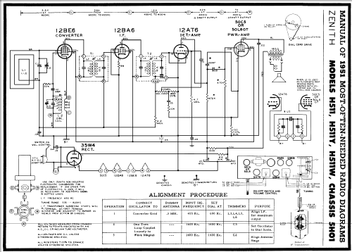
2 The Schematic Diagram
2.1 Input circuit
The RF - signal is picked up by the frame - antenna and coupled directly to g3 of the Pentagrid Converter 12BE6. L1 in combination with section C2 of the twin variable capacitor form the tuned input circuit. Trim capacitor C1 serves for fine - tuning the input circuit. Inductive fine tuning was not included.
The capacity variation achieved with C2 was measured using R&S KARU :
ΔC2 ≈ 27 ⇒ 460µµF, the max. value of trim capacitor was C1 ≈ 30 µµF. The max. sum - capacity resulted therefore in (C1 + C2) max = 490 µµF.
Lower frequency boundary of MW band
Assuming a half activated trim capacitor C1 = 15 pF, and neglecting wiring and tube input capacity (they are negligible compared to (C1 + C2)max), one gets (C1 + C2) = 475 µµF.
In the left lower corner of the schematic one can see the specified MW reception band Δf MW = 535 ⇒ 1620 kcs.
With a circuit capacity of 475 µµF the low frequency band boundary of 535 kcs is reached by using an inductance of L1 = 186 µH.
Upper frequence boundary of MW band
Using the measured minimum capacity of C2 (27 µµF), and the half activated trim capacitor C1 =15 µµF, on ends up with a minimum circuit capacity of (C1+C2) = 42 pF. Together with the inductance of the frame anrenna L1 = 186 µH the upper limit of the reception frequency is 1800 kcs.
Taking into account the wiring and tube input capacity of a few µµF, the input circuit can be expected to cover the full specified MW frequency range of 535 - 1620 kcs.
2.2 Oscillator Circuit
The oscillator has to cover a frequency range, displaced above the reception range by the intermedidiate frequency:
Δf Reception = 535 ⇒ 1620 kcs, IF = 455 kcs ⇒ Δf osc = 990 ⇒ 2075 kcs.
The oscillator circuit is composed of the coil L2 = 127 µH (measured using R&S LARU), section C3 of the tuning capacitor, and the trim capacitor C1osc. The hot end of the oscillator circuit is coupled to g1 of the 12BE6 via 110 µµF, while inductive feedback is made into the cathode circuit of the 12BE6. .
R&S KARU measurement of the capacity variation of the oscillator section of the tuning capacitor gave ΔC3 = 45 ⇒ 210 µµF, while the max. capacity of the associated trim capacitor was less than that of the input circuit: C1osc ≈ 20 µµF.
Again assuming a half activated trim capacitor C1osc, the measured L and C - values result in the following oscillator frequency range:
L2 = 127 µH, Δ(C3) +C1osc = 55 ⇒ 220 pF ⇒ Δf osc = 952 ⇒ 1904 kcs
This means that the highest frequency that the radio can receive is (1904 - 455) kcs = 1449 kcs, way below the specified 1620 kcs!
If we re- calculate the oscillator frequency range assuming a completely de-activated oscillator trim capacitor C1osc, we get:
L2 = 127 µH, Δ(C3) = 45 ⇒ 210 pF ⇒ Δf Osz = 974 ⇒ 2105 kcs
This result sounds a bit better, since the values are now closer to the required Δf Osz = 990 ⇒ 2075 kcs, but one has to keep in mind that up to this point, the frequency range calculation had been done neglecting the wiring and 12BE6 grid capacity.
In reality, the uppermost oscillator frequency reached in this radio with completely de-activated trim capacitor was 1900 kcs, corresponding to a max. reception frequency of 1445 KHz.
Using L2 = 127 µH this means that the min. circuit capacity was 55 µµF, i.e. 10 µµF more than the min. value of the tuning capacitor without C1osc. This meant that the wiring and tube input produced the same capacity as a half activated trim capacitor.
Conclusion:
What we see is: Δf reception ≈ 500 ⇒ 1445 kcs versus
what we should see: Δf reception = 535 ⇒ 1620 kcs
The solution to this mysterious discrepancy will be presented in section 4.3.
2.3 IF - Amplifier and Demodulator
The IF - signal leaving the 12BE6 mixer is amplified in a varable mu penthode 12BA6 and demodulated in the diode section of a 12AT6.
The IF - filters were tuned to the then standard IF frequency of 455 kcs. While the 1st IF - filter ('95-1101') represents a standard bandpass filter with parallel capacitors of ≈ 120 µµF (not stated in schematic), the 2nd filter ('95 1102') shows a pecularity that is also found in many other ZENITH radios:
Both, AGC and AF voltage are derived from the neutral end of this filter (green line).
2 capacitors are connected to this neutral end: one leading to the cathode of the 12AT6 (i.e. bridging the volume control pot), another is put in series with the IF - circuit capacitor.
A comparison with the schematic of the ZENITH G503 shows, that the latter capacitor was erroneously introduced into the schematic of the H511.
All IF - filter capacitors were encircled in blue
ZENITH H511 Ch=5H01 (1951) ZENITH G503 Ch=5G41 (1950)
Apart from models H511 and G503 one can find IF - filter neutral end capacitors drawn in a somewhat unusal fashion in other ZENITH models. Here are two more examples:
ZENITH F615L Ch=6F05 (1962?) ZENITH 6G004Y Ch=6C41 (1947)
Model 6G004Y used IF - filters with capacitive tuning, but even here, one can see the unusal capacitor combination with the neutral end in common.
In section 4.4 below, it will be shown that with the goal of reducing production costs, ZENITH had adopted the habit of integrating these capacitors into the filter base plates.
2.4 AF - Amplifier
The triode system of the 12AT7 served as AF - preamplifier, the beam power pethode 50C5 - or alternatively its predecessor 50L6GT - served as the speaker amplifier.
2.5 Power Supply
A one-way tapped filament rectifier tube 35W4 was used for the plate voltage supply. The 6-8V / 150 mA dial lamp was placed across one half of the filament, thus avoiding current overload during the tube warm-up time when filaments are still cold and current flow in the heater circuit is accordingly high.
Since both, the filament and the sum of all plate currents pass trough the tube heaters, the dial lamp shows only a dark glow as long as the tubes are cold. Once the tubes reach full emission, the dial lamp shows normal glow. A clever invention!
3 The mechanical setup
Some pictures of the chassis I received for repair:
Apart from re-stuffling the electrolytic capacitor (60 µF / 150 V und 20 µF/150V), nothing was changed on the chassis top,
Most of the capacitors and resistors had already been replaced by modern components, before I received the chassis.
4 Repair actvity
The owner complained about the poor sensitivity of the radio. The defects responsible for this problem will be described below.
4.1 Test setup
The test setup comprised the following equipment:
- Signal generator SMLR with 30% / 1 kc AM modulation.
- Output of SMLR fed into homebrew frequency counter and calibrated attenuator TG-950, .
- The attenuated RF - signal leaving the attenuator was coupled into a small loop antenna (originating from a PANASONIC SA-PM17 Receiver). RF - voltage at the feedpoint of the frame antenna ≈ 2 mVpp
- The receiver frame antenna picks up the the modulated AM - signal
- The 1 kc AF signal amplitude at available at the speaker terminals was recorded using a PM3310.oscilloscope
- 50 cs hum suppresion was achieved by using a 2nd order LC - high pass filter: C = 165 nF, L = 157 mH ⇒ fg ≈1 kc (resonance) between speaker and oscilloscope.
4.2 Loop antenna
The owner communicated that he had bought the radio in the US without speaker and cardboard rear panel. As one can see on the RM model page of the ZENITH H511, the loop antenna was attached to the rear panel.
To keep the radio as close as possible to the original state, he had decided to produce a replica of the rear panel , but instead of glueing the antenna on the cardboard (difficult job!) he modified the design in such a way that the RF Litz wire coulb be directly wound on the rear panel body
Original Replica
Measuring the inductance of the replica coil, I found 290 µH instead of the required 186 µH derived in section 2.1. After removing a couple of turns, I ended up with 185 µH.
With the help of trim capacitor C1, the input circuit could now be properly tuned.
4.3 Oscillator
The insufficient oscillator frequency range proved to be somewhat problematic.
In most radios provisions are made for inductive and capacitive alignment of the oscillator circuit - in the present case only capacitve corrections can be made.through trim capacitor C1osc.
Since, even with completely de-activated trimmer, the frequency range covered by turning the tuning capacitor from fully in to fully out was too narrow - - the problem had to be caused by an undiscovered "parasitic" capacitor.
This can have several reasons:
- Excessive input capacity of the oscillator grid of the 12BE6 pentagrid converter (the tube found in the set was branded DELCO).
- Humidity absorbtion into the oscillator coil (water has a dielectric constant ε = 81, as oppposed to air ε ≈ 1).
- Aging of the dielectric constant of oscillator coil grouting agent (wax in the present case).
af 1.) Swapping the 12BE6 with a tube made by LORENZ didn't have any influence.
Zu 2.) In order to exclude scenario no 2, the oscillotor coil was demounted and heated until the wax liquified and dropped out. The following pictures show the coil before and after heat treatment.
The change of the coil intrinsic capacity was checked via the change of its resonance frequency.
These measurements were made using the 'EXCITER' described here.
Prior to the heat treatment the intrinsic resonance frequency was 3,488 mcs. With the already mentioned inductivity of the oscillator coil of 127 µH one gets a parallel capacity of 16,4 µµF.
After the heat treatment only a marginal freuence change of a few kcs was observed. This means that a potential influence of infiltrated humidity could also be excluded.
In order to exclude reason number 3 cited above, i.e. the influence of aged wax, one could removed the wax by immersion into a wax dissolving solvent. But fearing that the coil might disintegrate, I preferred to refrain from this adverure.
Finally, my old friend RM member Hans M. Knoll proposed to closely inspect the wiring of the oscillator circuit.
So I demounted the compete tuning capacitor and found a surprise: While on its top side both, input and oscillator stator had a parallel trimmer, there was another trimmer (red circle) on the bottom of the oscillator stator! The adjustment screw if this trimmer was so firmly tightened that it took brute force to open it.
Tuning capacitor top Tuning capacitor bottom
⇐ Hidden trimmer position
With the tuning unit in place one could in principle see the adjustmant screw of the bottom trim capacitor, but its function did not occurr to me.
The oscillator circuit capacity values of the demounted tuning unit were then verified with the trim capcitors tightened and loosened, respectively, and the following encouraging results were obtained:
Oscillator tuning section capacity range
- upper trimmer fully loosended, lower trimmer fully tightened: Cmin = 38 µµF, Cmax = 202 µµF
- upper and lower trimmer fully loosended: Cmin = 11 µµF, Cmax = 175 µµF
This means that the neglected bottom trim capacitor introduced a parallel capacity of
C1osc,bottom = 27 µµF (!) into the oscillator circuit. This led to the observed effect of the frequency tuning range being too narrow.
After cleaning, replacing the rubber grommets, and adjusting the bottom trim capacitor to 10 µµF, the tuning unit was put back in place.
After releasing the bottom trim capacitor from initially 27 µµF to 10 µµF, the oscillator frquency range could now be trimmed to cover the entire specified MW range.
Surprisingly, the existence of the oscillator bottom trimmer was neither mentioned in the ZENITH alignment instructions nor in the schematic illustration of the chassis components.


Apparently, the bottom oscillator trimmer belonged to the components that were set during production and no further adlustment was anticipated. The fact that in the present case this trimmer was found to be firmly 'banged' could be a consequence of an earlier unsuccessful repair attempt.
4.4 The IF - Filters
The most difficult part of this repair job was encountered during the attempt to re-align the IF - filters. In the course of previous alignment attempts the ferrite cores ('tuning slugs') had been damaged and could not be moved any more.
Here are a few pictures of the first IF - Filter:
The coil - bodies of both IF - filters consisted of 0,4 mm ( 0.016'') thick impregnated paper cylinders of 7 mm (0.28'') outer diameter with 3 lateral notches, one of which bore regularly spaced corrugations.
 ZENITH loved IF - filters, the slugs of which could both be operated from the top, such that the filter bottom was free for a fixation bolt.
For this purpose, the tuning slugs had central hexagonal holes. A special alignment wrench had been devised, consisting of a slim cylindrical stem and a hex - key shaped lower end (see sketch on the left).
When fully inserted, the hex - key end would penetrate into the lower tuning slug, and this could be rotated without affecting the position of the upper. By lifting the wrench a little, the hex key end would leave the lower slug and penetrate the upper, which could then be adjusted separately.
Since the coil bodies had no thread, ZENITH relied on the tuning slugs to cut their own thread into the paper coil body as they were inserted. For a one-time factory adjustment procedure this was a clever and cost-saving approach, but it was definitely not apt for repetitive re-alignment. The rough surface of the ferrite tuning slugs would inevitably damage the inner surface of the paper body and grip was lost for good.
Unfortunately, none of the 4 slugs could be rotated in the present case, since all hex key holes had been damaged as a consequence of previous repair attempts. So I decided to simply destroy the tuning slugs and install suitable replacements. .
For this purpose I inserted a steel hex key into the pre - damaged tuning slugs. A slight twist broke the brittle ferrite slugs and the bits could be easily removed from the coil body. This approach works because of the gauge difference between continental EU and US hex keys. There is one EU hex key that has a slightly smaller gauge than the US original. Twisting it puts just the right shear force on the ferrite.
Prior to this action one should make sure that the coil body can't move in its holder. The coil wires are very delicate and if the coil body moves / rotates, they can easily be ripped off! So please use some epoxy to guarantee a stable seat of the coil body with respect to the filter base! Obviuosly, the paper coil body will slightly expand when destroying the tuning slugs. But in the present case, this did not cause any problems.
Now we are at the point, where the coil bodies can be refilled. In the EU you can get coil bodies with 5 or 6 mm outer dia. Since the ZENITH coil bodies have an inner dia of 6.2 mm (0.25''), one is tempted to insert the 6 mm type. Please, don't try that!. As was mentioned before, the original ZENITH paper coil bodies have lateral notches which reduce the inner dia just below 6mm. If you force the 6 mm type inside, the paper will inevitably break and you're lost.
To be on the safe side, I used the 5mm outer dia type which comes in differents lengths and tuning slugs with different magnetic permeabilitis for use in different frequency band applications.
Tuning slugs with yelow, magenta and white color dot are for Medium and Long Wave application, those marked red and green are for Short Wave.
This picture shows the original first IF - Filter with the 5 mm coil body insert next to it. When using tuning slugs with yellow color dot, little insertion into the IF coils was necessary to reach resonance at 455 kcs. Due to perspective distortion, this is not clear in the picture.
Obviously, the tuning slugs were inserted from the outer side of the coils to avoid core over-coupling.
It should be mentioned that the filter circuits are loosely coupled. This means, that tuning one circuit has very little influence on the other circuit. This means that for the alignment procedure one can intitially remove the upper slug and tune the lower. After the lower is tuned to 455 kHz, the upper slug is inserted and the upper circuit is tuned without interfering with the resonance point of the lower circuit.
In the present case this was verified by monitoring the resonance frequency of the lower circuit while tuning the upper circuit. Since no significant frequency shift was observed one can be sure that the mutual influence of the correct tuning points is small.
Looking at the interior of ZENITH IF - filters, the question arises where they hid the capacitors (marked with blue circles in the schematic)
The answer: They were almost invisibly accommodated between the two base plates
The soldering terminals were shaped like little 'fans', and a Mica washer was placed between them, the sandwich setup forming Mica plate capacitors . .
Coil soldering terminals: red and green, Mica washer: blue
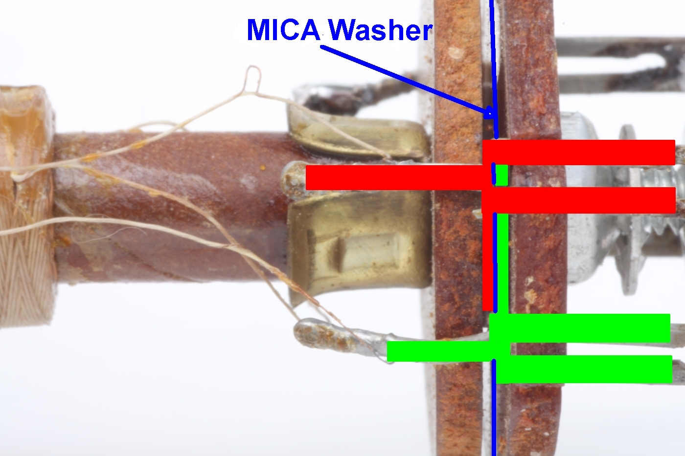
Using this crafty sandwich construction, and thus avoiding extermal capacitors, ZENITH managed to reduce production costs.
It may go without saying that the same trick was used for the capacitor combination at the neutral end of the second IF - filter.
6 Final remarks
One can conclude that after the restauration, the radio is in working order, but that the sensitivty is still not overwhelming.
In view of the fact that ZENITH marketed the model H511 (and others like the recently discussed ZENITH Modell G503 Ch=5G41 ) as "Long Distance Radio" , I have a feeling as if this catchword was not really justified.
But maybe one should not have too high expectations when it comes to the sensitivity of standard AA5 receivers.
In any case, they were very flashy little radios!
My thanks go to Hans M. Knoll for his never tiring support.
Harald Giese
Harald Giese, 19.May.23