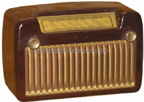
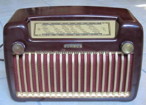
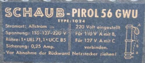
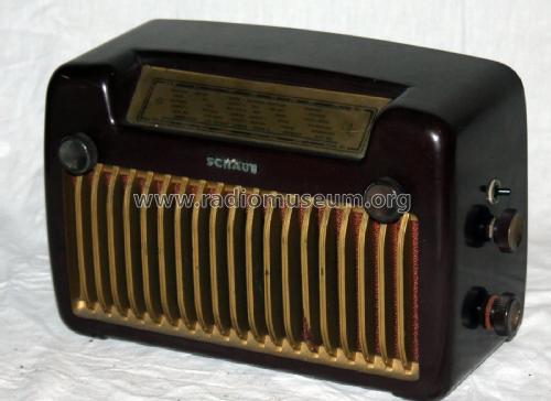
Pirol 1124 56GWU
Schaub und Schaub-Lorenz
- Pays
- Allemagne
- Fabricant / Marque
- Schaub und Schaub-Lorenz
- Année
- 1955–1957

- Catégorie
- Radio - ou tuner d'après la guerre 1939-45
- Radiomuseum.org ID
- 19604

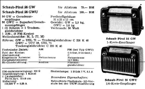
56 GW / 56 GWU
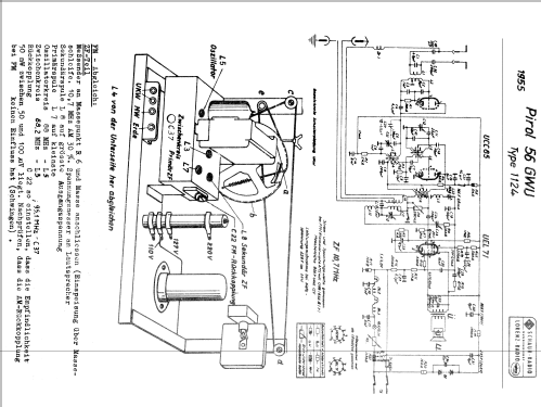
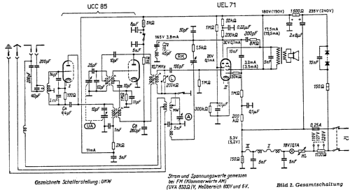

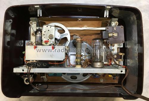
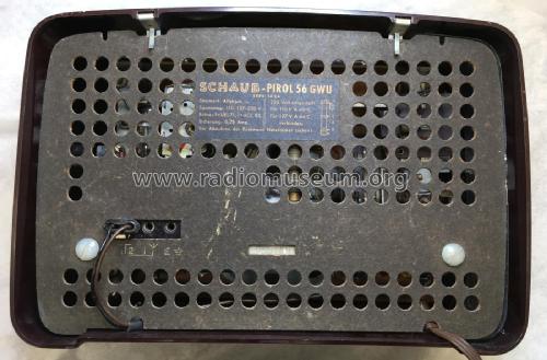
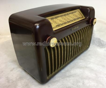

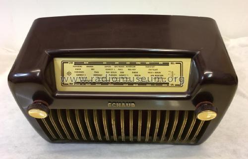
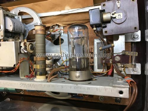
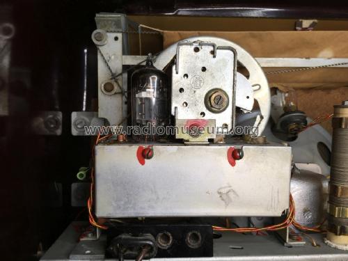
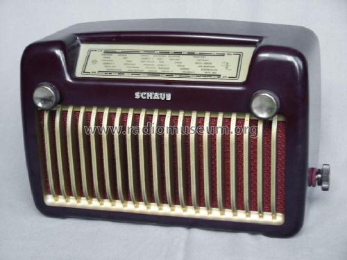
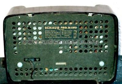
Bild aus ebay

Bild aus ebay


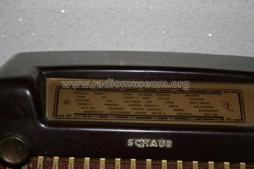
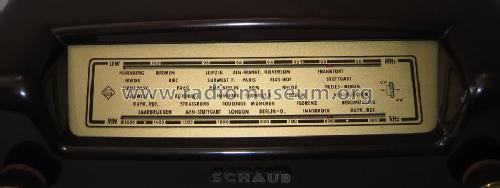
D Schaub Pirol 56 GWU Skala
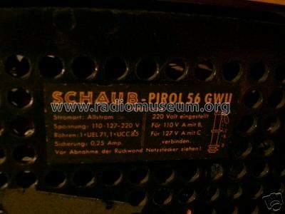
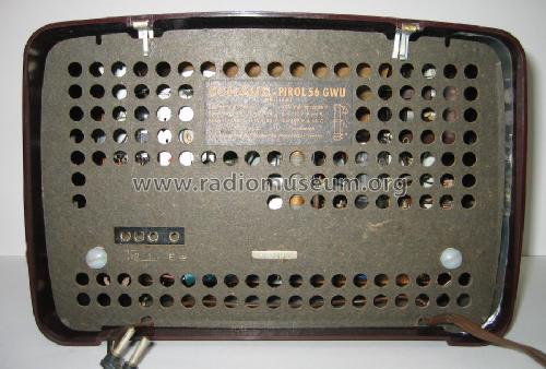
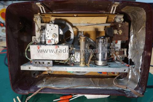
D Schaub Pirol 56 GWU Rückwand

Firmenlogo "Schaub" fehlt.


Cliquez sur la vignette du schéma pour le demander en tant que document gratuit.
- No. de tubes
- 2
- Principe général
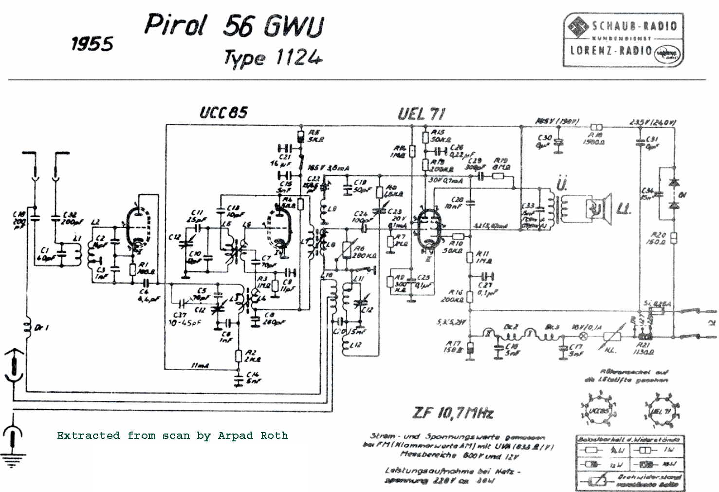
- Super hétérodyne, circuits FI avec réaction; FI/IF -/10700 kHz
- Circuits accordés
- 1 Circuits MA (AM) 5 Circuits MF (FM)
- Gammes d'ondes
- PO et FM
- Tension / type courant
- Appareil tous courants (CA / CC) / 110; 127; 220 Volt
- Haut-parleur
- HP dynamique à aimant permanent + bobine mobile / Ø 13 cm = 5.1 inch
- Matière
- Boitier en bakélite
- De Radiomuseum.org
- Modèle: Pirol 1124 56GWU - Schaub und Schaub-Lorenz
- Forme
- Modèle de table sans poussoirs, modèle cheminée
- Dimensions (LHP)
- 310 x 210 x 130 mm / 12.2 x 8.3 x 5.1 inch
- Remarques
-
Für UKW = Superhet mit ZF-Rückkopplung.
- Poids net
- 2.8 kg / 6 lb 2.7 oz (6.167 lb)
- Prix de mise sur le marché
- 109.00 DM
- Source extérieure
- Erb
- Schémathèque (1)
- -- Original-techn. papers.
- D'autres Modèles
-
Vous pourrez trouver sous ce lien 974 modèles d'appareils, 833 avec des images et 691 avec des schémas.
Tous les appareils de Schaub und Schaub-Lorenz
Collections
Le modèle Pirol 1124 fait partie des collections des membres suivants.
Contributions du forum pour ce modèle: Schaub und Schaub-: Pirol 1124 56GWU
Discussions: 5 | Publications: 7
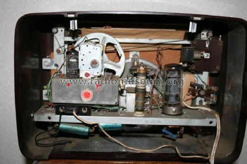
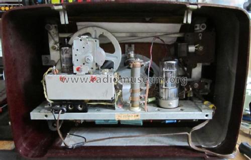
Bei ebay fiel mir dieses Gerät auf, weil rechts neben der UEL71 eine weitere Miniaturröhre eingebaut war. Nach Ersteigerung bot sich ein kurioses Bild: Offensichtlich schon ab Werk (darauf weisen die gleichen Drähte, Widerstände und Kondensatortypen hin) wurde ein TA-Zusatz eingebaut:

Dazu gehören der TA-Eingang unter dem Heizwiderstand und die zusätzliche UC92, die als NF-Vorstufe arbeitet.
An der linken Seitenwand befindet sich ein Kippschalter zum Umschalten Radio/TA und ein Poti zur Lautstärkeeinstellung.

Auch die Seitenwand mit dem gleichen Knopf wie für die HF-Lautstärkeeinstellung darunter weist auf den Werkseinbau hin:

Ist sowas woanders schon mal aufgetaucht? Der Aufwand in ein so simples Radio noch eine zusätzliche NF-Stufe, einen TA-Eingang, Lautstärke-Poti und Schalter einzubauen ist ja beträchtlich.....
Martin Steyer, 26.Dec.19
Fellow Radiophiles:
After a long wait for a lucky auction and with the kind assistance of RM member Mr. Georg Beckmann, who bought and shipped this radio from Germany to me, I got the opportunity to study this fascinating but simple AM-FM two-tube radio. The interesting findings in the operation of this radio also stimulated correspondence between myself and two radio expert RM members Mr. Hans Knoll and Prof. Dietmar Rudolph.
Introduction
Other articles already posted under this Schaub Pirol 56GWU model cover the basic operational details of this radio; I plan to focus on measurements, analysis and observed operational characteristics. The AM part of the radio uses the UEL71 Tetrode/Pentode in a particularly well designed circuit with a single tuned resonant RF tank circuit, where the tetrode serves as regenerative detector and the pentode serves as audio power output tube. The FM part of the radio simply adds a slightly modified superhet front end box with a UCC85 dual triode, that converts the early German 88-100MHz FM band to the 10.7MHz IF, which is then slope-detected by the Tetrode in the UEL71. The audio section, like the rest of this simple radio, is very well thought out, without noticeable distortion and a pleasantly shaped bass boost. One could enjoy listening to the pleasant sound from this radio for hours and forget that it was the simplest AM-FM design in the Schaub product line.
The AM section
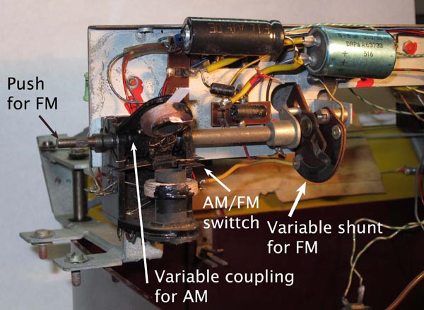
The variable transformer coupling for the AM antenna and the separate regeneration control made it easy to obtain very nice sound with adequate selectivity from the AM section.
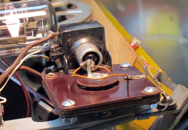 Regeneration - I found the regeneration control exceptionally independent of frequency. In other words, you could set the regeneration control at a relatively high regeneration level, just short of oscillation, and tune the entire AM dial without the appearance of oscillations from excessive regeneration anywhere on the dial. While the oscillation point for the regeneration control on the front of the radio varied less than 5o of rotation throughout the dial, the nearly contemporary Grundig Gloria 51GW has a regeneration control that must be rotated some 30o as new stations are tuned throughout the dial. The control in the picture includes the power switch and the variable capacitor (measured 3pF-180pF) that sets the amount of regenerative positive feedback from the detecting Tetrode plate to the tuned tank circuit. Achieving frequency independence in the regeneration control involves a careful account for the variation in Q of the tank circuit L11-C12 as a function of frequency, which can be minimized by a proper ballance of shunt vs series coil losses. The frequency response of the feedback coil circuit also affects the oscillation point as a function of frequency.
 The regeneration control arrived with a partial repair, where 3 of the 4 rivets had been replaced by screws. In the process of completing the repair of the control, I had occasion to take it appart. The original 3pF-180pF range was too wide, where the oscillation point was at less than 1/4 of the shaft rotation. The construction includes 2 thin brass rotor foils sandwiched between 2 aluminun foils separated by phenolic insulators. I moved the middle aliminum stator foil under the end aluminun stator foil to reduce the total capacitance range to 3pF-55pF. The regeneration control now operates with greater ease.
Homodyne detection - After years of playing with several regenerative sets, I have learned to operate them in synchronized additive homodyne detection mode. This a form of synchronous detection where the regeneration control is advanced slightly past the point of oscillation and the tuning is adjusted carefully until the beat whistle disappears and the oscillating frequency of the detector is locked to the incomming station carrier. This radio had a particularly easy and stable lock range, on the order of +/-200Hz at 1030kHz (WBZ 30 miles away in Boston radiation 50kW), judging by the lowest pitch that appears when carrier lock is lost. Very weak signals have a much narrower lock range. Once the local oscillation is locked, the regeneration control can be varied in and out of oscillation without loss of lock. This is a further testament to the frequency independence of the regeneration control.
The Homodyne oscillation amplitude at the detector Tetrode control grid was never more than a few hundred mVp-p. The tetrode always operated without clipping in it's power law transconductance (gm) region. The soft non-linearity of this power law serves to stabilize oscillation amplitude without significantly distorting the much smaller modulation envelope riding over the local oscillation. The advantage of this type of additive homodyne detection over simple regeneration is that the distortion that often accompanies non-oscillating regenerative detection drops dramatically and bandwidth also widens to produce the sensation of High-Fidelity reception. The drop in distortion can be understood from the drop in percent modulation, as the local oscillation greatly boosts the carrier amplitude. With the positive side of the envelope so far from the negative side of the envelope, the grid leak diode looks like a nearly ideal diode where the grid diode is completely off for negative RF peaks and is on with a fixed resistance on the positive peaks. Under homodyne detection, I am hard-pressed to find a better sounding AM radio of the same size in my collection.
But Homodyne detection has it's caveats. First off, some of the energy at the oscillating frequency is radiated back out the AM antenna. When the oscillator is locked, this is perfectly harmless, and actually benefits the reception of radios nearby as the total carrier energy is boosted, which facilitates detection and improves fidelity. When the oscillation looses lock, then whistles are audible in the Pirol as well as in any nearby radio. But this energy is very small and probably will not reach your neighbours (see "A few RF interference measurements").
Additive vs Multiplicative synchronous AM detection - The very clean Homodyne operation of this radio served to clear up a misconception on my part. Ideal synchronous detection differs from the self-oscillating homodyne detection in this radio in one fundamental way. While ideal synchronous detection pushes all neighboring channels into super-sonic frequency beats outside the transmitted 5kHz audio bandwidth, thus greatly benefiting selectivity, no such benefit exists with the Homodyne operation of this radio. In fact, as I advance the regenerative control for stronger local oscillations, the selectivity drops and I can hear strong neighboring stations. The intuitive explanation is that with this kind of Homodyne detection, a relatively low amplitude oscillation is developed that is equivalent to receiving a station with a very strong carrier, but relatively low modulation. This helps envelope detection for the desired station but does nothing to prevent envelope detection for the neighboring stations. This form of homodyne detection can be described as aditive, with the incomming signal and the local oscillation added at the envelope detector, while ideal synchronous detection is multiplicative. Purely multiplicative detection does not let input signals reach the output without being heterodyne first. The reduced selectivity when the regenerative control is advanced further past the oscillation point is due to the fact that bandwidth and selectivity are at their peak at the oscillation point and drop when regeneration is increased or decreased away from this optimum. But it is this softening of selectivity with over-regeneration that makes for nice reproduction of higher audio frequencies under Homodyne detection. Signal gain is also at a peak at the point of oscillation and drops on either side of the oscillation point.
The FM section
 The regenerative slope detection of the IF frequency was the last circuit configuration that was used before the standard FM superhet topology with IF amplifiers stages and FM discriminators was universally adopted for all price ranges. Before this combination of standard FM front end followed by slope detection, the innexpensive FM detection configuration was with super regenerative detectors, which had the disadvantage of radiating interference back to the antenna.
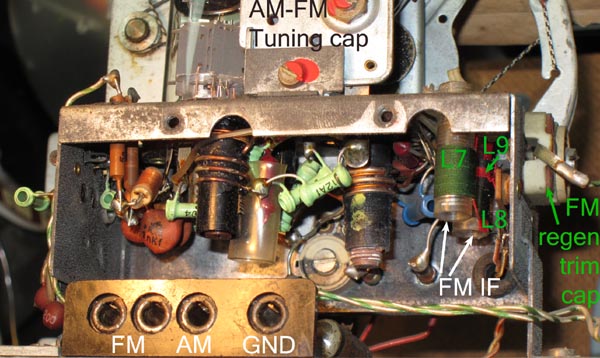
This FM section does not radiate spurious energy at the channel frequency and it also operates with the better selectivity that superhet conversion affords with a single-tuned RF tank and a double tuned standard IF transformer. The original alignment instructions aim to tune the two IF transformer coils L7 and L8 to the same 10.7MHz frequency, as is customarily done with IF transformers. 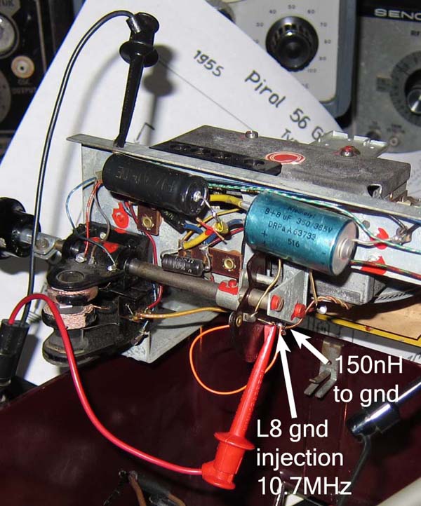 The goal is to produce a peaked response with reasonably linear side slopes for grid-leak detection by the Tetrode in the UEL71. The sharpness of the peak is controlled by the feedback circuit L9-C22 into the secondary IF coil L8 and also by the adjustable R6<200kΩ load. The original alignment sought to control this peak shape with a recommendation that 50uV-100uV at the input with 30%AM modulation on an RF test signal should produce 50mW at the 5Ω speaker. The recommended alignment procedure makes use of the parasitic inductance in the ground leg of L8 to inject the fixed frequency AM-modulated 10.7MHz signal. I measured approximately 150nH to ground at the ground leg of L8. The identical primary and scondary coils measure 12.6uH each with Q=60 and have a measured coupling factor k=0.02 at 200kHz. With this signal injection, a small voltage injection results in greatly magnified voltage at the secondary L8 because of impedance transformation. A full explanation of this signal injection method is found at "Resonanz-Transormation". Injecting the signal this way at the secondary also means that secondary L8 is tuned for peak response, while the primary L7 is tuned for peak absorption, or a minimum response in the speaker output.
Modern 75kHz FM deviation - The FM deviation in the 1950's was usually 40kHz peak, as opposed to the modern 75kHz (deviation figures from private email with Prof. Dietmar Rudolph). This means that the original FM-IF alignment procedure is likely to produce more distortion for weaker signals when the value of R6 is increased for greater sensitivity and the FM-IF response is sharpened, which produces steeper more non-linear detection slopes on either side of the 10.7MHz peak.
 After studying frequency sweeps of the IF transformer with its secondary regeneration, it became clear to me that an alternative alignment could produce a very nice tilted top frequency response with very selective sharp slopes on the sides. Now the carefully tilted detection slope is at the center of the channel and undistorted sound reproduction is obtained for stations that are weak enough to produce hiss. Click on the figure to see a range of sweep shapes and top tilts, that is obtained when the L8 secondary load R6 is varied. The effect of the variation in R6 is roughly equivalent to a variation in the internal FM regeneration control C22. The probe point for these sweep photos was the control grid of the ouput pentode at UEL71 pin3. The sweep response at the pentode plate is distorted by the bass boost filter response, and the slope detector tetrode plate still has 10.7MHz content that would have been disturbed by the ~10pF load of standard 10x 10Meg scope probe. A short circuit can be applied across the output transformer primary or across the speaker terminals to eliminate the sweep buzz in te speaker.
The only significant difference between this alignment and the recommended alignment is that the L7 primary and the L8 secondary are aligned to 10.65MHz and 10.75MHz respectively, instead of 10.7MHz. When the primary and secondary are aligned to the same frequency as shown in the following simulation on the left, a variation in secondary loading or regeneration does not tilt the top of the response; it simply controls the degree of the under- or over-coupled response. The under-coupled response produces a single central peak, while the over coupled response produces twin peaks at identical height. The two LTspiceIV .AC simulations step the value of R6 with the parameter P. (Click the figures to enlarge). The input is an ideal 1Amp source, and the output result in volts can also be directly interpreted as a trans-impedance in Ohms.
 But if the primary and secondary are detuned from each other, as shown in the simulation on the right, then a variation in secondary loading or regeneration will also affect the tilt at the top of the response. The double-tuned transformer affords an extra degree of freedom for alignment, as compared to a single-tuned transformer. With the double tuned transformer, over-coupled response can be maintained for steep skirt selectivity, while the top is adjustable for a slope that drops smoothly by about 50% from one peak to the other. It is not important to chose which coil gets which frequency, as long as they are 100kHz appart and centered with respect to 10.7MHz.
Joe Sousa, 07.Apr.13
Fellow Radiophiles, this set was introduced by Funkschau in 1955.
Regards,
-Joe
Funkschau 1955, volume 9, page 194.
Interesting designs: A small FM superheterodyne set
The inexpensive single tuned circuit AM set keeps loosing its reason to exist because it can't receive FM broadcasts. Super-regenerative FM receivers are discontinued due to their unpleasant radiated interference. The Schaub Pirol 56 GWU was created for the low end of the superheterodyne price range. It operates with a single tuned circuit in the AM band and uses 6 tuned circuits for FM. Figure 1 shows the block diagram.
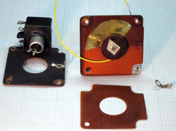
The low cost of 109 DM, which exceeds the price of a single tuned circuit AM radio by only about 40 DM, is realized by using a mass produced FM front end building block that is also used in the standard sized FM receivers from this year's production cycle. This front end block does the RF preamplification, frequency conversion and IF amplification with six tuned circuits: An input FM bandpass filter, a tuned tank load at the RF preamp anode, a tuned oscillator tank, and both tuned tank circuits of the IF bandpass filters. This block uses the series string heater UCC85.
The FM input filter provides wide band pre-selection and IF stability. Oscillator leakage is also blocked from the antenna, so that the “Bundespost” regulations can be easily met. The RF preamp is realized with an intermediate grounding scheme (“Zwischenbasis”). (Figure 2)
The intermediate grounding circuit grounds the input coil at a tap point to achieve high gain with uncritical neutralization (C4=4.4pF from the Anode to the input coil). At resonance, the tunable anode circuit has a resistance around 10kW to yield amplification around 60-fold.
The second triode works as a self-oscillating additive mixer. The RF signal is fed into the grid coil of the oscillator. The internal resistance of the triode is increased by regenerative feedback (voltage drop across C8=260pF) at IF frequencies. The IF bandpass filter drives the grid-leak tetrode detector in the UEL71, which operates as a slope detector. The IF filter secondary is loaded by a 200kW volume control. The value of this resistor is reduced to lower the volume from strong stations. This reduced resistance dampens the IF filter, widens the IF bandwidth and the slope detection becomes more linear with a resulting increase in sound reproduction quality. A preset regenerative feedback from the grid-leak detector anode via capacitor C22 increases FM sensitivity to 80uV for an output power of 50mW with 22.5kHz(rms) FM deviation. Thus is the goal of this receiver achieved, which is to receive local FM stations.
The AM section is implemented with a single tuned circuit with variable antenna coupling and regenerative grid leak detector. The Lorenz UEL71 dual is applied here for the detector tube and output tube. The grid bias for the output tube is taken across the 150W resistor in the power supply circuit and is filtered with 200kW and 0.1uF.
A small amount of negative feedback from the anode of the output tube to the anode of the grid-leak detector (8MW, 300pF) yields a bass boost. Just two 8uF capacitors and a 1.5kW resistor are enough to filter the low current that is drained by the anode circuits. The small heater voltage drop for both tubes makes 110V AC/DC operation possible, which includes a dial lamp that is protected by an additional current surge limiting resistor.
Despite the added FM section, the construction of the chassis in this receiver takes hardly more effort than that of a simple single tuned AM radio.
Translated by Joe Sousa from a scan kindly provided by Mr. Eckhard Kull and posted in the original German by Prof. Dietmar Rudolph at
Die interessante Schaltung: Ein UKW-Kleinsuper.
Joe Sousa, 02.Apr.13
Das Gerät wurde in der Funkschau 1955 vorgestellt.
Funkschau 1955, H.9, S194
Die interessante Schaltung: Ein UKW-Kleinsuper
Der billige AM-Einkreiser verliert immer mehr seine Bedeutung, weil damit kein UKW-Empfang möglich ist. Pendelempfänger schalten wegen der unangenehmen Störstrahlung aus. Als UKW-Kleinempfänger niedrigster Preisklasse wurde deshalb der Schaub Pirol 56 GWU geschaffen. Er arbeitet im MW Bereich als Einkreiser und für UKW als Sechskreissuper. Bild 1 zeigt die Blockschaltung.

Der günstige Preis von 109 DM, der nur ca. 40 DM über den Preisen normaler Einkreiser liegt, ergibt sich zum Teil daraus, daß für die UKW-Stufe ein serienmäßiger UKW-Baustein aus den Schaub Normalempfängern dieses Jahrganges verwendet wird. Er enthält für die Hf-Verstärkung, Mischung und Zf-Verstärkung sechs Kreise: ein UKW-Eingangsbandfilter, einen abgestimmten Zwischenkreis an der Anode der Hf-Vorstufe, einen Oszillatorkreis und die beiden Kreise des Zf-Bandfillers. Als Röhre dient die Allstrom-Doppeltriode UCC85.
Das UKW-Eingangsbandfilter erhöht die Weitabselektion und die Zf-Festigkeit. Ferner wird die Antennenstörstrahlung der Oszillatoroberwelle herabgesetzt, so daß die Vorschriften der Bundespost mit Sicherheit eingehalten werden können. Die Hf-Vorstufe besitzt eine Zwischenbasisschaltung (Bild 2).

Die Anzapfung ist so gewählt, daß sich eine hohe Verstärkung bei unkritischer Neutralisation ergibt (C 4 = 4,4 pF von der Anode zum Eingangskreis). Der abstimmbare Anodenkreis hat einen Resonanzwiderstand von etwa 10 kΩ und ergibt eine etwa 60-fache Hf-Verstärkung.
Das zweite Triodensystem arbeitet in selbstschwingender Mischschaltung. Die Hf-Spannung wird in die Gitterspule des Oszillators eingespeist. Der Innenwiderstand der Triode ist für die Zwischenfrequenz durch eine Rückkopplung (Spannungsabfall an C 8 = 260pF) entdämpft. Das Zf-Bandfilter führt zum Audionsystem der Röhre UEL71, das hier als Flankengleichrichter arbeitet. Der Sekundärkreis des Zf-Filters ist mit dem 200kΩ Lautstärkeregler überbrückt. Beim Herabregeln von starken Sendern wird dieser Widerstandswert verkleinert. Dadurch wird das Filter bedämpft, die Bandbreite vergrößert sich, die Demodulationsflanke wird geradliniger und die Wiedergabegüte steigt. Eine fest eingestellte Rückkopplung von der Anode des Audions über den Kondensator C 22 erhöht die UKW-Empfindlichkeit auf 80μV für eine Ausgangsleistung von 50mW bei 22,5kHz Frequenzhub. Damit ist der Hauptzweck dieses kleinen Empfängers sichergestellt: das Programm des örtlichen UKW-Senders aufzunehmen.
Der AM-Teil ist als Einkreiser mit veränderlicher Antennenkopplung und rückgekoppeltem Audion geschaltet. Für das Audion und die Endstufe wird die Lorenz Verbundröhre UEL71 verwendet. Die Gittervorspannung für die Endröhre fällt an dem 150Ω Widerstand im Netzteil ab und wird durch 200kΩ und 0,1μF gesiebt.
Eine leichte Gegenkopplung von der Anode des Endröhrensystems zur Anode des Audions (8MΩ, 300pF) bewirkt eine Baßanhebung. Bei dem geringen Stromverbrauch genügen 2 * 8μF und ein 1,5kΩ Widerstand im Netzteil zur Siebung des gesamten Anodenstromes. Der geringe Heizspannungsbedarf der beiden Röhren ermöglicht auch an 110-V-Netzen einen einzigen Allstromheizkreis mit einer zusätzlichen durch einen Heißleiter geschützten Skalenlampe.
Der Chassisaufbau des Empfängers weist trotz des UKW-Superteiles kaum mehr Aufwand als ein einfacher AM Einkreiser auf.
Mein Dank gilt Eckhard Kull für die Bereitstellung des Scans.
MfG DR
Dietmar Rudolph † 6.1.22, 25.Mar.13
Fellow Radiophiles,
I had a recent email exchange with John Hunt. He owns the well known web page about the Fremodyne super regenerative FM detector at http://cool386.tripod.com/fremodyne/fremodyne.html.
John sent me a very nice analysis of the operation of the Schaub Pirol 56GWU. The following is that analysis by John Hunt.
In an earlier email I had told John that the FM detector was super-regenerative. John has correctly shown otherwise. The difference is based on the frequencies involved and on the component values in the schematic, rather than on topology.
Enjoy,
-Joe

Hi Joe, Interesting to see the info on the Pirol; another of those cheap German sets of the 50's...but this is the first two valve set of its kind I've seen. I question the detector being superregenerative though.
There's an optimum ratio of quench to receiving frequency. As we can see the IF for the VHF part is 10.7MHz. That's pushing it a bit for a superregenerative detector. It's also why we almost never see superregenerative receivers for the MW broadcast band; the optimum quench would be quite audible.
My interpretation of the Pirol circuit is this: Starting with the MW section because that's easy, L10 is the aerial primary winding, with a tapping low down for a long wire aerial. The top tapping makes use of the VHF transmission line for the MW aerial.
L11/C12 is the MW tuned circuit which feeds the UEL71 tetrode grid via grid leak C24/R7. Ignore L8 in the signal path; as it's a 10.7Mc coil it will have minimal effect on the MW signal passing through.
L12 is the regeneration feedback winding with C23 used to adjust the amount of regeneration.
The audio output is conventional with negative feedback/tone correction provided by C29 and R19.
Presumably, the volume control for MW is performed by C24, the regeneration control. An often used method, but not good because you lose selectivity as the "volume" is reduced.
All completely standard practice so far. Turning now to the VHF portion, the UCC85 (26V heater version of 6AQ8), first triode accepts the aerial input from L1/L2. This circuit is broadly resonant around the VHF broadcast band by means of C1. The low Q due to aerial loading will see to it that the bandwidth is broad enough for the whole band.
The first triode is operating as a neutralised RF amp, with C4 providing the antiphase feedback into the lower part of L2. Nothing unusual here.
L3 is the plate load for the RF amp and feeds the amplified VHF signal into the converter stage based around the second triode.
C12/C5/C37 tune the RF circuit with C37 being the trimmer to bring the RF circuit into correct tracking with the local oscillator.
The frequency converter which converts the VHF signal to 10.7Mc/s is also nothing unusual. It's a standard oscillator circuit.
The VHF is fed into the converter grid via C7 from L4. R3/C9 are the oscillator grid leak.
As this kind of oscillator requires both sides of the tuning condenser to be floating, they have got around this by coupling the tuning condenser by another isolated winding, L5, and can thus earth the moving plates.
L7/L8 is the 10.7Mc/s IF transformer. C11 is the padder capacitor to make the local oscillator run above the RF.
This time round, the 10.7Mc/s signal is fed to the detector triode by the same grid leak condenser as used for MW (C24), and the tetrode now operates like it did before but at 10.7Mc/s and not 550-1600KHz as it does on MW.
Regeneration feedback is provided by C22 preset (this can be preset because the frequency is now fixed), and L9 the feedback winding.
C19 is the RF bypass for both MW and 10.7Mc/s which is standard for any regenerative detector. However, bypassing is never perfect here and enough RF exists to provide regeneration by C22 (10.7Mc) or C24(MW).
R8 prevents the MW feedback circuit shunting away too much of the 10.7Mc/s signal given that C24 would shunt away too much at 10.7Mc/s. Presumably because of the more critical nature of C22's adjustment, R6 is provided for the FM volume control simply by progressively shorting out the IF signal.
As a by product of this, regeneration will also be reduced (because of loading L8, and thus L9) to further assist volume reduction. Now, as to C22's adjustment. If this is taken to the point just before oscillation like for AM, the bandwidth will be too narrow for the 75Kc/s deviation of FM. So it would appear that to set C22, R6 is set to full volume and C22 set to max capacitance just before distortion (from a narrowing of bandwidth) sets in.
This way, reducing R6 will only broaden bandwidth and to no ill effect.
So, in my opinion this set uses a regenerative detector for FM, and not a super regen one. The reasons being:
1)C24/R7 would give a quench of around 10Kc/s which is very audible,
2) there is no quench filtering between the detector plate and audio output stage,
3)10.7Mc/s is rather low for efficient superregenerative operation.
I would expect the performance of this receiver on MW to be like any other two valve set; good loudspeaker volume on all local stations.
For VHF, my guess is would be like a straight VHF regenerative set but with a little more gain. It would bring in local stations OK but not a DX set.
I did have a Telefunken Rhythmus 52GW which had an untuned RF stage and one IF amplifier...my version was the later one that had a ratio detector instead of the slope detector. Sensitivity was poor. It would bring in the main Sydney stations 80km away but really needed the outdoor aerial to do so properly.
In fact, I could easily find out what the Pirol would be like as it just so happens I have a prefabricated tuning head from a Sansui tuner/amp. It uses two 6CW4's for the RF and a 6AQ8 for the converter. Just have to feed the IF o/p into a grid leak detector and provide a bit of feedback.
There is a book I recommend you try to get "Superregenerative Receivers" by J.R. Whitehead and printed by the Cambridge University Press. There are portions viewable on Google Books if you want to look it up. Any in depth analysis of SR Rx's unfortunately requires lots of maths.
All the best for the New Year,
John
Joe Sousa, 03.Jan.10