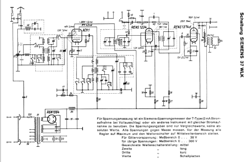
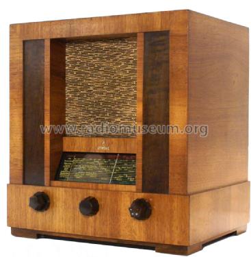
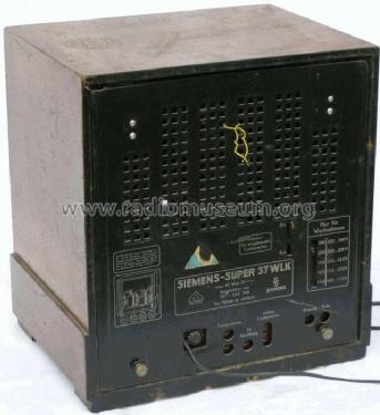
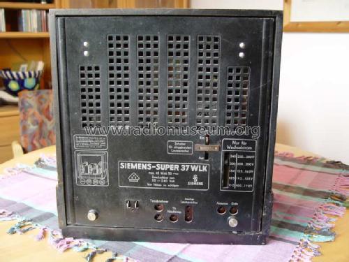
Reflex-Super 37WLK
Siemens (& Halske, -Schuckert Werke SSW, Electrogeräte); Berlin, München
- Paese
- Germania
- Produttore / Marca
- Siemens (& Halske, -Schuckert Werke SSW, Electrogeräte); Berlin, München
- Anno
- 1934/1935
- Categoria
- Radio (o sintonizzatore del dopoguerra WW2)
- Radiomuseum.org ID
- 5419
Org.Pl.
Org.Pl.
Org.Pl.
Org.Pl.
Org.Pl.

Org.Pl.

Org.Pl.
Schwandt
Schwandt

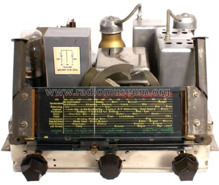


Skala ist neu angefertigt!
Clicca sulla miniatura dello schema per richiederlo come documento gratuito.
- Numero di tubi
- 4
- Principio generale
- Supereterodina (in generale); ZF/IF 468 kHz; Reflex
- N. di circuiti accordati
- 5 Circuiti Mod. Amp. (AM)
- Gamme d'onda
- Onde medie (OM), lunghe (OL) e corte (OC).
- Tensioni di funzionamento
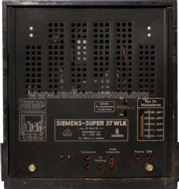
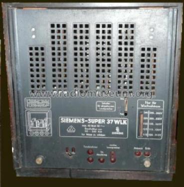
- Alimentazione a corrente alternata (CA) / 110; 125; 150; 220; 240 Volt
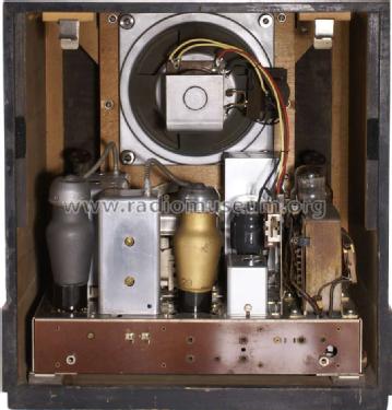
- Altoparlante
- AP elettrodinamico (bobina mobile e bobina di eccitazione/di campo)
- Materiali
- Mobile in legno
- Radiomuseum.org
- Modello: Reflex-Super 37WLK - Siemens & Halske, -Schuckert
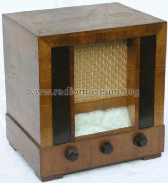
- Forma
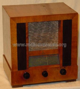
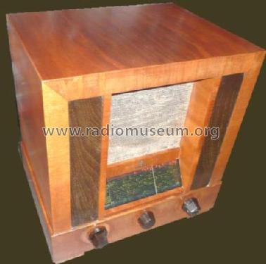
- Soprammobile verticale (sviluppato in altezza; no cattedrale, sin decorazioni).
- Dimensioni (LxAxP)
- 380 x 410 x 290 mm / 15 x 16.1 x 11.4 inch
- Annotazioni
- Reflex-Schaltung (2. Rö); Ferritkernspule.
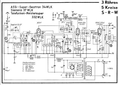
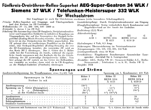
AEG 34WLK und Telefunken 332WLK.
- Peso netto
- 15.2 kg / 33 lb 7.7 oz (33.48 lb)
- Prezzo nel primo anno
- 284.00 RM
- Fonte dei dati
- Radio-Katalog Fricke, Radio Groß-Vertrieb, 1934/35 / Radiokatalog Band 1, Ernst Erb
- Riferimenti schemi
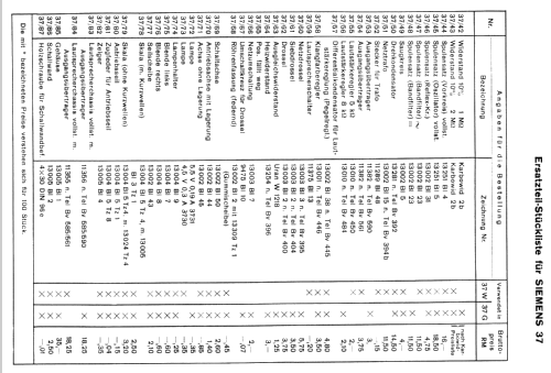
- Lange+Schenk+FS-Röhrenbestückung
- Bibliografia
- Radio-Katalog, Mix & Genest Hansawerke, 1935
- Letteratura / Schemi (1)
- -- Original-techn. papers.
- Bibliografia immagini
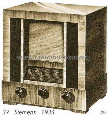
- Das Modell ist im «Radiokatalog» (Erb) abgebildet.
- Altri modelli
-
In questo link sono elencati 2543 modelli, di cui 2154 con immagini e 1347 con schemi.
Elenco delle radio e altri apparecchi della Siemens (& Halske, -Schuckert Werke SSW, Electrogeräte); Berlin, München
Collezioni
Il modello Reflex-Super fa parte delle collezioni dei seguenti membri.
Discussioni nel forum su questo modello: Siemens & Halske, -: Reflex-Super 37WLK
Argomenti: 3 | Articoli: 5
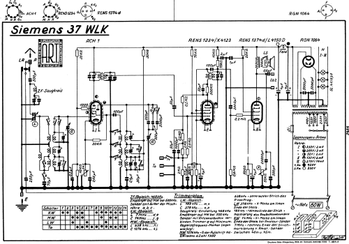
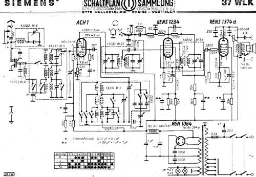
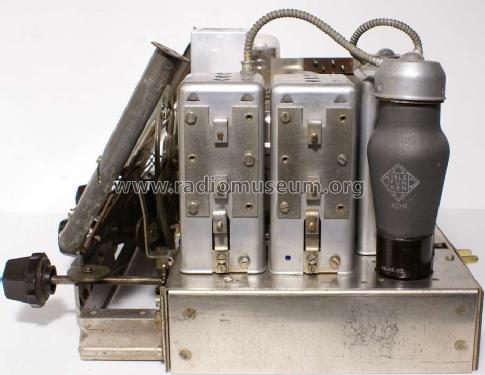
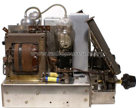
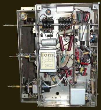
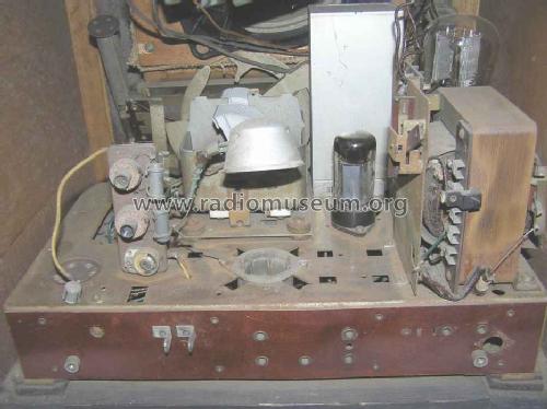
This interesting German set dates back to 1934 and relies on the same circuit and chassis of the AEG 34WLK and Telefunken 332WLK. Some components, like the sensitivity potentiometer mechanically connected with a split capacitor and coaxial with the tone control potentiometer are unique and their substitution with other components would be almost impossible. Fortunately the mechanical and electrical quality of these components is excellent so that the chances of finding them in perfect working conditions are high. Also the band selector is robust and beautifully designed and makes very pleasing operating this receiver. The set that I have restored did not look as a particularly critical case but first looks can be deceiving (they were). The purpose of this note does not concern the description of the sophisticated circuit of this receiver but only the sharing of the experience acquired in solving some specific problems. For the sake of brevity, the topics will be treated separately.
1) Preliminary operations. Be sure to get as much information as possible before removing any component or connection, take many pictures under appropriate light conditions. This recommendation is valid in general, to intercept every circuit variation introduced after the construction but is mandatory for the 37WLK because it is possible to find two different insertions of the second I.F. transformer in its reflex circuit.
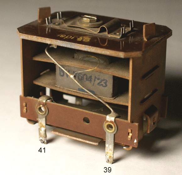
Figure 1 - The second I.F. transformer could have been inserted in two different ways in the reflex circuit
See the very interesting post by Professor Dietmar Rudolph and be sure to identify which circuit has been adopted on your set. Get the corresponding electrical diagram among the available ones. Identify also the components that have been substituted with others with different values.
2) Capacitors. Check with care all accessible capacitors and restore them when required (most capacitors are of the impregnated paper type and it is not difficult to insert a new component inside the old glass casing in order to preserve the original look). Some capacitors are contained in a box (Figure 2) that, fortunately, can be easily opened.

Figure 2 – Capacitor box
There are, however, some capacitors that require special attention. The two 4 uF capacitors of the HV filter are contained inside a large metal case and are not electrolytic as could be deduced by the symbols used in some diagrams; they are paper capacitors and their substitution could be unnecessary.

Figure 3 – Some diagrams of the 37WLK denote the filter capacitors as electrolytic
Two other critical capacitors are the 5000 pF ones inserted on the HV windings of the transformer that operate under an high AC voltage (420 V).
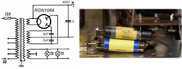
Figure 4 – Capacitors on the HV windings
For safety reasons it would be advisable to substitute these capacitors with Y1 or Y2 class ones; it is however almost impossible to find components of this kind small enough to enter into the original casings. A small milling on ceramic Y class capacitors can reach this goal (seal the glass tube with epoxy after inserting the milled capacitors). Other capacitors that could require a substitution because of capacity variations are the padding ones, contained inside the oscillator can (see the specific note on disassembling this subsystem); these capacitors are shown in Figure 5 and their values (indicated only on some diagrams) are 250 pF, 330 pF and 5000 pF.
.jpg)
Figure 5 – Padding capacitors
The circuit inside this can contains also a mica capacitor (30 pF) that could require a substitution (I have preferred silver mica types in these substitutions). Note the cracked filling compound indicated by the arrow in Figure 5.
3) Trimmers. The mica foil trimmers in the I.F. transformers are mechanically connected to a mica capacitor mounted on the opposite side, obtained by painting with a conductive paint both sides of a mica foil. These capacitors are not protected and their actual capacitance can be a small fraction of the original one.
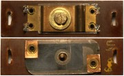
Figure 6 – The two sides of the I.F. transformer trimmers
Trying to separate these capacitors from the trimmers would waste the trimmers and spoil the integrity of the receiver; it is preferable to add a parallel capacitor in order to be able to tune these transformers on the I.F. of 468 KHz (in my case it has been necessary to add 220 pF on the primary and secondary windings of the first transformer, something less on the tuned circuit of the second transformer). It can be useful to know that the maximal excursion of the trimmer is approximately 36 pF, that one turn of the screw corresponds to a variation of approximately 5 KHz and that the useful number of turns is 3. After removing the first I.F. transformer can it is possible to observe that the distance between the windings can be changed in order to modify, if desired, the selectivity.
4) Mechanical problems. These have been the worst problems and appeared only during the first trial to align the receiver. At that stage both I.F. transformers and the oscillator unit had been removed from the set for the operations described above and reassembled while the can containing the input filters had been left in place (it does not contain capacitors to be checked and/or substituted). While aligning the input circuit it was noticed that the tuning of some circuits was outside the range of variation of the trimmers; moreover small knocks on the can led to variations in the tuned frequencies. After disassembling this unit, the discouraging situation shown in Figure 7 became evident: all rivets that should have kept in place the mobile parts of the trimmers were broken. Some rivets were also crossed by wires and this prevented their substitution with screws. Moreover it was impossible to find rivets with this small size in Italy and the problem could be eventually solved only thanks to the generous help of Professor Dietmar Rudolph who sent me perfect replacements. Mounting the new rivets has not been trivial and has required the construction of a pair of small T-shaped adapters that have allowed to carry out the whole operation without dismantling the unit. Removing this unit from the receiver and even opening the can is a delicate operation (see the specific notes).

Figure 7 – Brocken rivets inside the input tuning unit
5) Other electrical operations. All remaining electrical operations consisted in restoring the values of a pair of resistors that had been substituted with others and in substituting, for safety reasons, two wires with new, cloth covered, ones with proper color (brown) and look; it has been possible to leave in place all remaining wires.
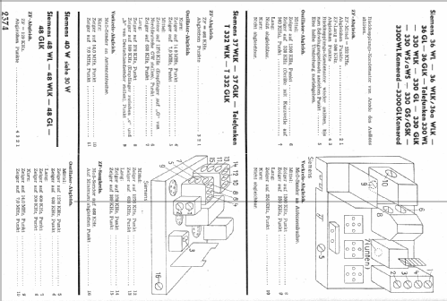
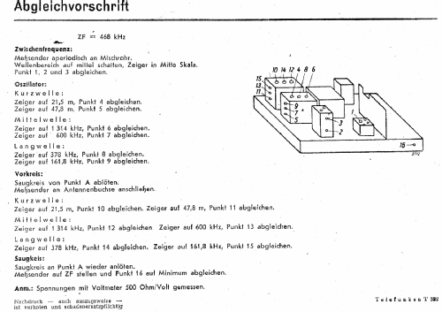
6) Alignment. The sequence of the alignment operations is clearly described on one of the documents that can be downloaded in the RM page dedicated to this set. Unfortunately, however, the indications concerning the trimmers and the variable coils reported on this document did not correspond to the situation of my set (the same can be repeated for the 37WLK of Professor Rudolph). The correct mapping for these receivers (and, probably, many others) is that reported in Figure 8.

Figure 8 – Alignment trimmers and variable coils for the SH 37WLK
After aligning the set, a check on the bandwidth of the I.F. channel has confirmed that it was working properly. This check can be performed by injecting a non modulated signal on the grid of the ACH1 and observing the output of the I.F. chain on the plate of the RENS1234 (in the very peculiar circuit of this set the plate acts as detector, see the excellent article by Professor Dietmar Rudolph). In my case the obtained results are reported in Figure 9.

Figure 9 – Measured bandwidth of the I.F. channel
7) Background hum. The heart of the design of this radio set is the sophisticated reflex circuit around the RENS1234. The high impedance of this circuit makes it sensitive to hum; the screen under the chassis is, under this point of view, absolutely necessary. It is also important to ascertain its electrical connection with the chassis. Hum can be introduced also by an improper connection of the field coil of the loudspeaker (see the post Hum with electrodynamic loudspeakers).
8) Microphonics of the RENS1234. The socket of the RENS1234 is connected to the chassis by means of a rubber suspension in order to reduce its microphonics. This suspension was in pieces. It would have been possible to cut properly a sheet of rubber in order to perform a complete reconstruction; I have preferred a much simpler but effective solution based on the use of an O-ring with suitable dimension around the pins present on the chassis and on the socket (see Figure 10).

Figure 10 – RENS1234 elastic suspension
9) Line connection. The original connection to the line cable was performed by means of two small bars that have been often removed and substituted with a directly connected cable. It is not difficult to reconstruct this detail by using a small brass bar (Figure 11).

Figure 11 – Reconstructed line connector
10) Dismounting the oscillator and input tuning cans. While dismounting the I.F. transformers does not pose problems, dismounting these units from the receiver requires some care. It must be remembered, first of all, that there is a poorly reachable connection (clearly visible in Figure 5) between these cans and the variable capacitor. The second difficulty is a mechanical one since the extraction of the units, once that all electrical connections have been removed, looks impossible because of the interference with the hole on the chassis. Using a screwdriver or some other tool to bend slightly the interfering parts allows eventually the extraction. Also removing the metal screen requires some attention to avoid damages. The proper procedure is the following. (refer to Figure 12).

Figure 12 – Input tuning and oscillator cans
Remove the screws A. Remove the screw B and the screw in the same position on the opposite side. Do NOT remove or turn the screws D. Rotate gently the screws C counterclockwise as much as possible (pay attention to avoid applying excessive force at the end of the rotation range). Unsolder the internal wire from cap E leaving the wire free from tin residuals. It is now possible to remove the can. The procedure is identical for the oscillator unit. When the units are reassembled on the chassis remember the connections with the variable capacitor an pay attention to avoid bending the band selector contacts during the insertion (it can be useful to use some tape to keep them in place).
The loudspeaker unit mounted on my set was that designed by Siemens, apparently less common than the Telefunken one. It generated an high level of distortion because of mechanical interference between the voice coil and the air gap walls. It has been substituted with a Telefunken unit kindly sent by Professor Rudolph.

Figure 13 – The loudspeakers designed by Telefunken (left) and Siemens (right)
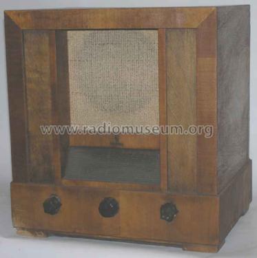
Reconstructing the dial glass has been a long adventure (see the post of Professor Dietmar Rudolph) that has not led to the desired final quality level; the obtained reproduction can however be considered as acceptable and is, anyhow, much better than digital prints.
Removing the black spots on the case has been another underestimated problem (solved using a solution of oxalic acid). The final finishing has been with natural wax, after three tampon applications of a solution of shellac (100 g/liter).

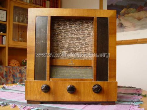
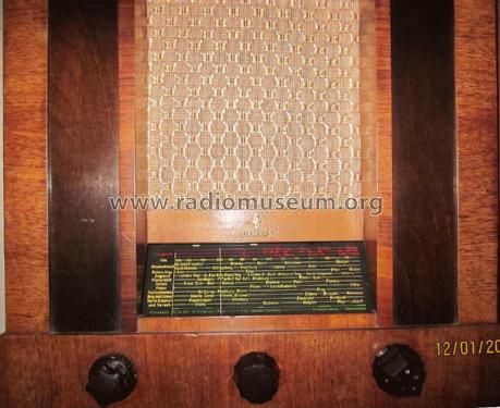
Figure 14 – The restored SH 37WLK
The overall performance of the receiver can be considered as good on all bands if compared with other good designs of the same period; no sensitivity measures have, however, been performed.
Roberto Guidorzi, 30.Jan.12
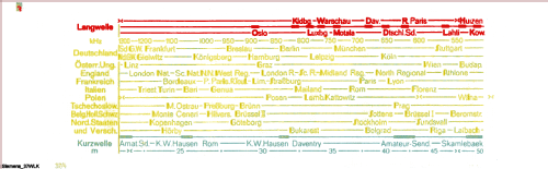
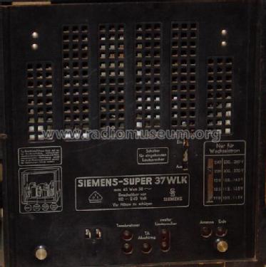
Das Problem mit verwischten Skalen hat schon fast jeder Sammler in unterschiedlicher Schwere erlebt. Bei einem Gerät mit Flutlichtskala stellt das eine besondere Schwierigkeit dar, weil die Beschriftung durch die seitliche Beleuchtung "erstrahlen" soll.
Bei meinem Gerät, das vor mehreren Jahren auf dem Flohmarkt erworben wurde, wurden von einem der Vorbesitzer alle Stationsnamen für die Mittelwelle (gelbe Farbe) herausgekratzt und durch einen schmalen Papierstreifen mit Frequenzmarken ersetzt. Aus den Verhältnissen nach dem WW2 war das vielleicht verständlich, weil gemäß dem damaligen Stockholmer Wellenplan sich praktisch alles geändert hatte, zumindest was deutschsprachige Stationen betraf.
Woher bekommt man eine Ersatzskala, oder zumindest eine Vorlage dafür? Das ist nicht einfach. Ich hatte großes Glück, daß damals Günther Abele große Teile seiner Sammlung verkaufte, um seine Bücher über "Historische Radios" zu finanzieren. Dabei war auch ein SH_37GLK, das parallele Gleichstrommodell mit identischer Skala. Auf Nachfrage bei Herrn Abele, ob ein Foto oder besser ein Scan der Skala zu bekommen sei, schlug er vor, die Skala auszubauen und mir zu schicken, damit ich den Scan selbst anfertigen kann.
Für diese Großzügigkeit sei ihm an dieser Stelle nochmals herzlich gedankt!
Zur damaligen Zeit noch ohne Scanner, fertigte ich verschiedene Farbkopien auf Papier und Folie an, die später auch noch eingescannt wurden.
Mit einer solchen Folie zwischen zwei Glasscheiben hatte das Gerät wieder eine (mehr schlechte als rechte) Skala.

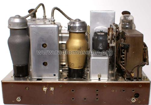
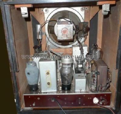
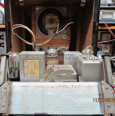
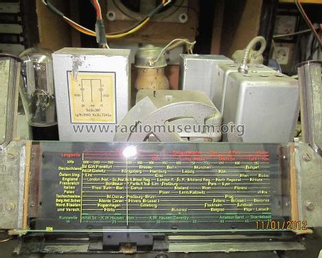
Hier sieht man das Chassis mit dieser Skala. Die Langwelle (in rot) und die Kurzwelle (in grün) waren nicht weggekratzt. Aber es war notwendig, hinter der Skala ein weißes Papier anzubringen, damit überhaupt etwas lesbar war.
Der Schirmbecher des ZF-Filters fehlte auch und wurde durch einen etwas eckigeren ersetzt. Ansonsten war der Zustand des Gerätes gut, was sich daran zeigte, daß die Blockkondensatoren noch einwandfrei waren.
Die Anschlüsse zum Lautsprecher wurden durch so lange Leitungen ersetzt, daß das Chassis herausgenommen werden kann, ohne dies ablöten zu müssen.
Dieser Zustand der Skala bestand einige Jahre. Im letzten Jahr hat mich ein italienischer Kollege angemailt, der ebenfalls ein Problem mit dieser Skala hatte. Er fand das Bild meiner Skala bei den Skalenbildern hier im RM.org und fragte nach einem Bild in besserer Auflösung. So kam eine sehr erfreuliche und fruchtbare Zusammenarbeit zustande, u.a. mit dem Resultat eines "Reprints" der Skala des SH_37WLK.

Hier sieht man die Lösung mit der Folie oben und die bedruckte Glasscheibe unten. In der rechten Hälfte liegt schwarzes Papier darunter und man sieht, daß dann mit der Folie nichts mehr erkennbar ist, wo hingegen die Flutlichtskala hier erst richtig zum "Leuchten" kommt.

Hier ist nun die neue Skala eingebaut, wodurch das Gerät wieder sein früheres Aussehen zurück erhält.

Auch meinem italienischen Kollegen, Roberto Gudorzi, sei an diese Stelle ganz herzlich gedankt!
MfG DR
Dietmar Rudolph † 6.1.22, 12.Jan.12
Die RENS1234, eigentlich konzipiert als HF - ZF Regelröhre mit geringem Regelspannungsbedarf, hat dabei 3 Funktionen zu erfüllen:
1. ZF-Verstärker, 2. Demodulator, 3. NF-Verstärker.
Bei üblichen Reflexschaltungen wird die Demodulation nicht in der gleichen Röhre gemacht. Hier ist es deshalb möglich, weil die RENS1234 eine Hexode ist und (etwas unüblich) das 2. Schirmgitter als Anode verwendet wird. Damit arbeitet sie de facto für die ZF- und NF-Verstärkung als Pentode(!). Die Anode wird als Gleichrichter-Diode für die Demodulation verwendet. Die dafür notwendige Katode wird durch die Raumladungswolke zwischen 2. Schirmgitter und Anode gebildet.
In einem einfachen Schaltbild (Wiesemann, H.: Praktische Funktechnik, Frankh, 1939, S. 19, Bild 29; Wurde ein Radio mit dieser Schaltung tatsächlich hergestellt?) sind die Signalwege eingetragen: magenta HF, cyan NF.
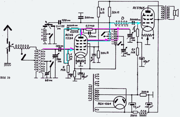
Wie man erkennt, ist die Anode der RENS1234 potentialmäßig auf 0 V und das 2. Schirmgitter fungiert als "Anode".
Im Schaltbild des Siemens 37WLK ist die RENS1234 in der ZF angeordnet. Auch hier sind die Signalwege eingetragen, zusammen mit einer (rot gezeichneten) Ersatz-Diode für die Demodulation.
Diese Ersatz-Diode zeigt, wie in dieser Verwendung der RENS1234 diese durch eine Pentode und eine Germanium-Diode ersetzt werden kann. (Falls "nur" die Funktion des Radios sichergestellt werden soll, aber die Kosten für eine RENS1234 eingespart werden sollen.)
Die RENS1234 (genau so wie die Mischhexode RENS1224) wurden nur kuzzeitig verbaut und sind heute eher selten zu erhalten. Im Jahre 1934 hat noch Otto Kappelmayer diese Hexoden über den grünen Klee gelobt.
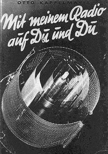

Die Bilder aus diesem Buch (Reprint: Maria Magdalene Freundlieb) zeigen einen Blick in den Systemaufbau von oben gesehen und ein Schnittbild der Röhre.
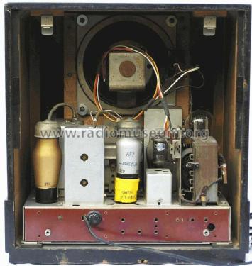
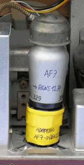
Die Frage der Ersatzröhre ist für praktische Verhältnisse zufriedenstellend lösbar. Aufgrund der "kurzen" Kennlinie der RENS1234 kommt keine echte Regelröhre in Betracht (z.B. AF3), weil deren Kennlinien "zu lang" sind, sondern z.B. eine AF7. Diese ist eigentlich nicht für Regelbetrieb vorgesehen, erfüllt aber hier ihren Zweck voll.
Weil alle Röhren im 37WLK Stiftröhren sind, ist eine AF7 als Röhre mit Topfsockel eigentlich nicht ganz passend, jedoch wurde sie verwendet, weil sie den Gitteranschluß oben hat - wie die RENS1234 auch.
Mit Hilfe eines Hexodensockels (z.B. von einer unbrauchbaren ACH1) und einer Topffassung läßt sich ein passender Adapter herstellen, wenn da noch eine Ge-Diode (Typ:AA... ; Spitzenkontakt, hochohmig) eingelötet wird. Mit etwas Schrumpfschlauch lassen sich die beiden Teile verbinden. Das nächste Bild zeigt eine solche "Ersatz"-RENS1234 in einem 37WLK. (Siehe auch die Bilder beim 37WLK)
Dietmar Rudolph
Dietmar Rudolph † 6.1.22, 06.May.06