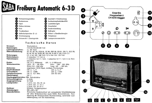
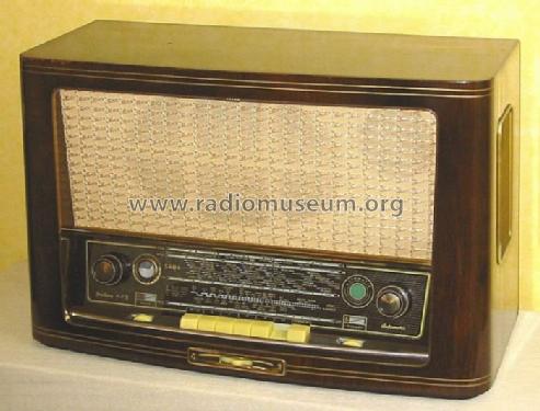
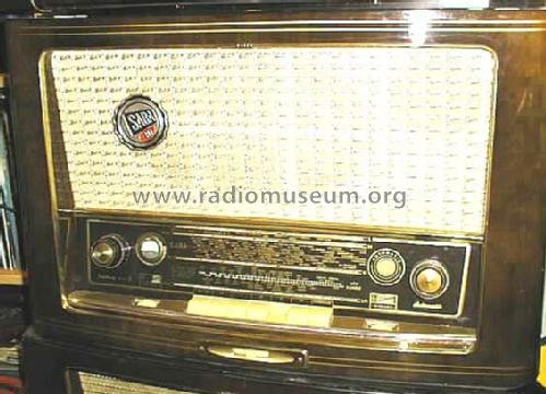
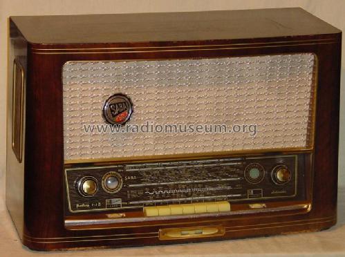
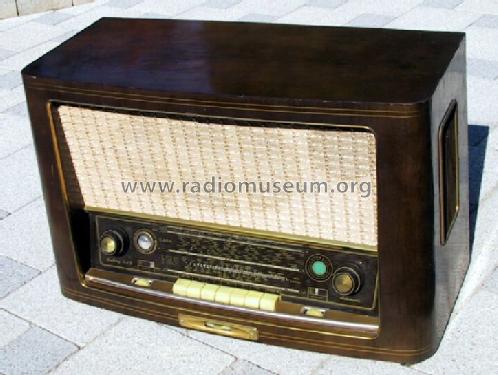
Freiburg Automatic 6-3D
SABA; Villingen
- Paese
- Germania
- Produttore / Marca
- SABA; Villingen
- Anno
- 1955/1956
- Categoria
- Radio (o sintonizzatore del dopoguerra WW2)
- Radiomuseum.org ID
- 6552
-
- Brand: Schwer & Söhne, GmbH


SABA Freiburg 6-3D Kondensatortausch
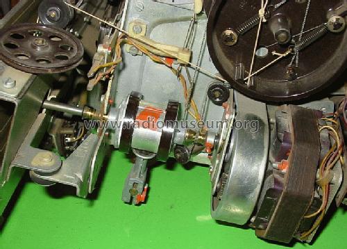
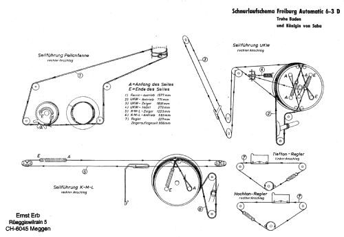
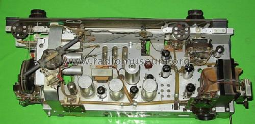
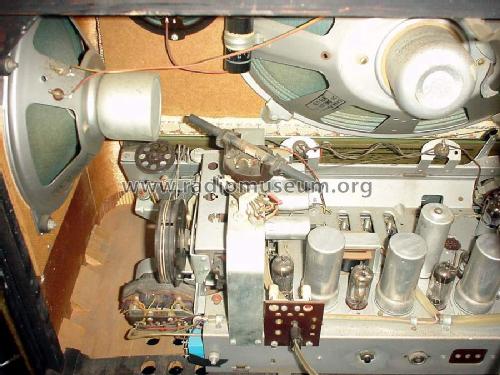
Kupplung des Skalenantriebs und Motor

D_SABA_1955_Freiburg 6-3D_Front
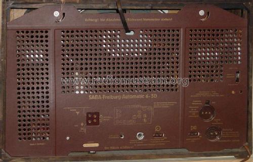
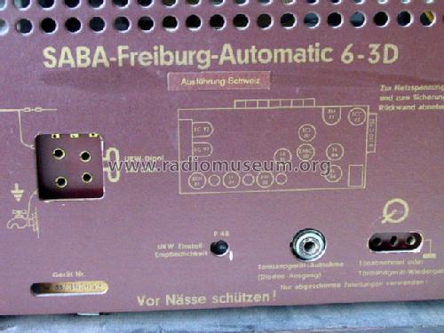
D_SABA_1955_Freiburg 6-3D_Rueckseite links
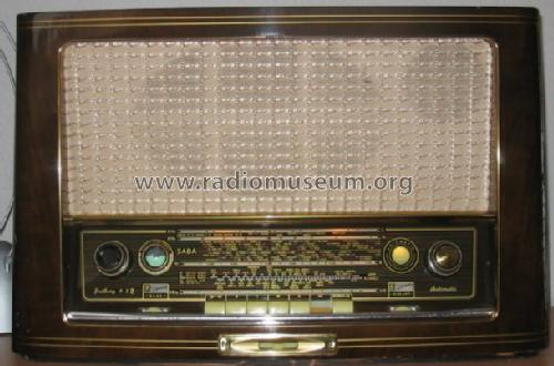
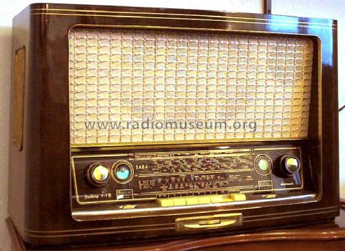
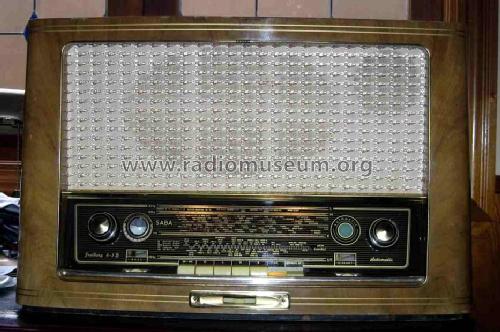
D_Saba_Freiburg6_3D_vorne
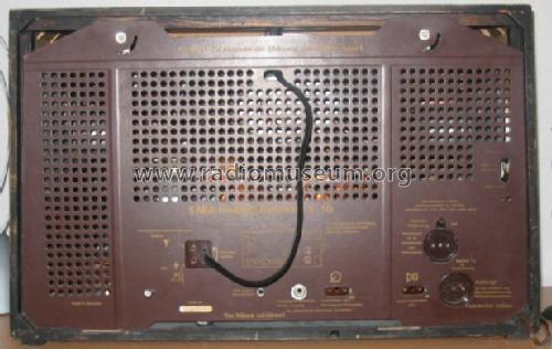
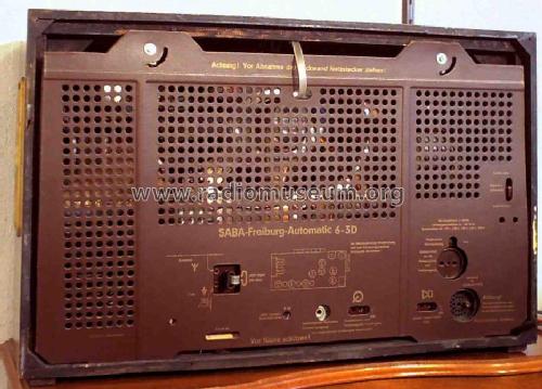
D_Saba_Freiburg6_3D_Rueckwand
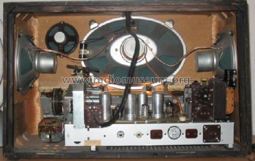
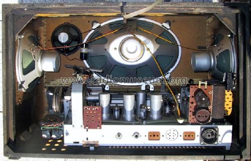
D_Saba_Freiburg_6_3D_innen
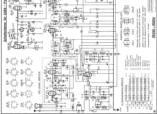
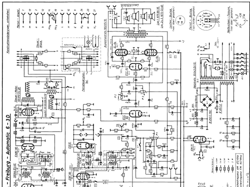
Clicca sulla miniatura dello schema per richiederlo come documento gratuito.
- Numero di tubi
- 12
- Numero di transistor
- Principio generale
- Supereterodina (in generale); ZF/IF 472/10700 kHz
- N. di circuiti accordati
- 10 Circuiti Mod. Amp. (AM) 13 Circuiti Mod. Freq. (FM)
- Gamme d'onda
- Onde medie (OM), lunghe (OL), corte (OC) e MF (FM).
- Particolarità
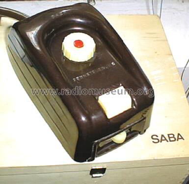
- Telecomando (con o senza filo)
- Tensioni di funzionamento
- Alimentazione a corrente alternata (CA) / 110; 125; 150; 220; 240 Volt
- Altoparlante
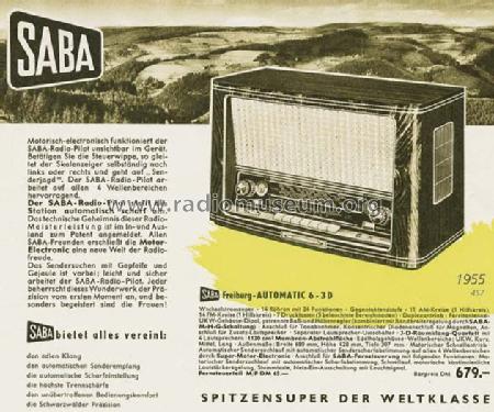
- 4 altoparlanti
- Potenza d'uscita
- 12 W (qualità ignota)
- Materiali
- Mobile in legno
- Radiomuseum.org
- Modello: Freiburg Automatic 6-3D - SABA; Villingen
- Forma
- Soprammobile con pulsantiera/tastiera.
- Dimensioni (LxAxP)
- 680 x 428 x 307 mm / 26.8 x 16.9 x 12.1 inch
- Annotazioni
-
Motorabstimmung; drehbare Ferritantenne..
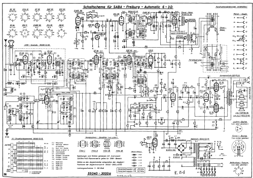
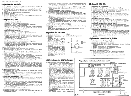
Abgleich (auch Steuerfilter)
Alignment (also automatic filter).
- Peso netto
- 18 kg / 39 lb 10.4 oz (39.648 lb)
- Prezzo nel primo anno
- 679.00 DM
- Fonte dei dati
- HdB d.Rdf-& Ferns-GrH 1955/56 / Radiokatalog Band 1, Ernst Erb
- Bibliografia
- -- Schematic (D.E. Ravalico, Il Radiolibro, 16° edizione, 1957, Hoepli)
- Letteratura / Schemi (1)
- - - Manufacturers Literature (Saba Katalog 1954)
- Letteratura / Schemi (2)
- -- Original-techn. papers.
- Bibliografia immagini
- Das Modell ist im «Radiokatalog» (Erb) abgebildet.
- Altri modelli
-
In questo link sono elencati 1652 modelli, di cui 1510 con immagini e 1190 con schemi.
Elenco delle radio e altri apparecchi della SABA; Villingen
Collezioni
Il modello Freiburg Automatic fa parte delle collezioni dei seguenti membri.
- Jochen Amend (D)
- Wolfgang Bauer (A)
- Gregorio Cavallaro (D)
- Hartmut Daniels † 22.11.16 (D)
- Mark Donen (USA)
- Hans-Werner Ellerbrock (D)
- Ulrich Fieseler (D)
- Bruno Gandolfo-Canepa (RCH)
- Jean-Louis HEYD (F)
- Axel Harten (D)
- Piotr Jachymczyk (PL)
- Hermann Jung (D)
- Heiner Krietsch (D)
- Friedrich Kutnik (D)
- Hartmut Litjes (D)
- Dietmar Luppold (D)
- Francisco Martins (P)
- Marcos Matos (P)
- A. P. (D)
- Stephan Pöhler (D)
- Aleksander Roś (PL)
- Gil Silva (P)
- Martin Steyer (D)
- Jürgen Tiedmann (D)
- Francisc VISKY (RO)
- Gerhard Waldherr (D)
- Georges Werts (B)
- Detlef Zimmermann (D)
Discussioni nel forum su questo modello: SABA; Villingen: Freiburg Automatic 6-3D
Argomenti: 9 | Articoli: 27
In response to a recent request, here is an English translation of the alignment instructions. The request asked for an English translation for 'alignment instructions for a SABA 6-3D'; however, a little research showed me that there are at least three different 6-3D models, all with different circuits and alignment procedures. The requested alignment procedure turned out to specifically match the SABA Freiburg Automatic 6-3D, so here it is.
SABA
[NOTE: The alignment ‘Point’ references below are based on the ‘Abgleichplan’ (alignment point location diagram) which is part of the original German alignment instructions, available here ('..._abgl').]
AM section alignment
- Connect a control voltage of about -4.5 V (- to test socket pin R, + to pin Y)
- Connect a loudspeaker and an audio voltmeter to the output socket, with the speaker switch in the middle position (both speakers ON)
- Set volume control to minimum (fully CCW)
- Press the ‘M’ (AM) key
- Press the ‘Automatic aus’ (Auto tuning OFF) key
- Connect an RF signal generator (472 kHz, 30% AM modulation) to the grid of the ECH 81 mixer through a 10 000pF (0.01µF) capacitor
IF alignment (472 kHz)
2-circuit filter, ‘Komb. Bdf. III’ (behind EBF 80)
- Use Point 1 to set for below-critical coupling.
- Adjust circuits I and II (Points 2 and 3) for maximum.
- Repeat steps 1 and 2 if necessary.
- Use Point 1 to set for critical coupling (maximum output voltage), then adjust for below-critical coupling by turning to the left (CCW) so that output voltage drops approx. 20%.
2-circuit filter, ‘Komb. Bdf. II’ (behind EF 89)
- Use Point 4 to set for below-critical coupling.
- Adjust circuits I and II (Points 5 and 6) for maximum.
- Repeat steps 5 and 6 if necessary.
- Use Point 4 to set for critical coupling (maximum output voltage), then adjust for below-critical coupling by turning to the left (CCW) so that output voltage drops approx. 20%.
2-circuit filter, ‘Komb. Bdf. I’ (behind ECH 81)
- Use Point 7 to set for below-critical coupling.
- Adjust circuits I and II (Points 8 and 9) for maximum.
- Repeat steps 9 and 10 if necessary.
- Use Point 7 to set for critical coupling (maximum output voltage), then adjust for below-critical coupling by turning to the right (CW) so that output voltage drops approx. 30%.
Alignment of auto tuning IF filter, 472 kHz
- Turn auto tuning on (press and release ‘Automatic aus’ key so that it is up)
- Connect a center-zero microammeter between pins M and Y of the test socket.
- Connect a DC voltmeter (input resistance 500k or more, set to 30 V range) between pins P and Y of test socket.
- Adjust for approx. 12V between pins P and Y as follows:
1. Turn coupling screw at Point 36 to the right (CW) until it stops, then back it out two turns.
2. Adjust the primary circuit at Point 37 to get a maximum reading on the DC voltmeter P.
3. Adjust the secondary circuit at Point 38 so that the meter appears to show a straight line between the lowest and highest readings, and set it back so that the center zero is along that line.
4. Repeat steps 2 and 3 as needed for correction.
When the auto tuning filter is correctly aligned, the tuning motor must not move. Detuning the signal generator slightly up or down should result in a corresponding movement of the motor, CW or CCW respectively. In addition, detuning the generator a set, larger amount above and below 472 kHz should produce equal deflection of the meter at M to either side of the center zero (discriminator symmetry).
IF trap alignment (472 kHz)
- Connect the signal generator to the antenna socket through an ‘artificial antenna’ (200pF and 400 ohms in series).
- Press the ‘L’ (LW) key, and turn the ferrite antenna to its stop (and turn it off). Adjust Point 10 on the antenna socket board to produce a minimum output meter reading. (This adjusts a trap that minimizes the possibility of the IF interfering with LW reception.)
Oscillator and antenna circuit (RF) alignment for SW/AM/LW
- Check: At the right-hand stop of the tuning dial, the indicator must be on the right end mark of the tuning scale, and the tuning capacitor must be fully closed.
1. Press the ‘K’ (SW) key. Set the signal generator and the tuning dial to 7.03 MHz (42.7 m). Adjust the oscillator and antenna circuit coils at Points 11 and 12 for maximum.
2. Set the signal generator and the tuning dial to 16.4 MHz (18.3 m). Adjust the oscillator and antenna circuit trimmer capacitors at Points 13 and 14 for maximum.
3. Repeat steps 1 and 2 if necessary.
- Turn the antenna switch to the ‘Ferritantenne’ (ferrite antenna) position.
- Loose-couple the signal generator into the ferrite antenna using another ferrite antenna or a few turns of wire.
- Press the ‘M’ (AM) key. Set the signal generator and tuning dial to 570 kHz. Adjust the oscillator and antenna coils at Points 15 and 16 for maximum.
5. Set the signal generator and tuning dial to 1520 kHz. Adjust the oscillator and antenna trimmer capacitors at points 18 and 19 for maximum.
6. Repeat steps 4 and 5 if necessary.
- Set the antenna switch to the ‘Außenantenne’ (external antenna) position.
- Connect the RF generator to the antenna socket through the ‘artificial antenna’.
7. Set the generator and tuning dial to 570 kHz. Adjust the ferrite antenna substitution coil at Point 17 for maximum.
8. Press the ‘L’ (LW) key. Set the signal generator and tuning dial to 190 kHz. Adjust the oscillator and antenna circuit coils at Points 20 and 21 for maximum.
9. Set the signal generator and tuning dial to 300 kHz. Adjust the oscillator and antenna circuit trimmer capacitors at Points 22 and 23 for maximum.
10. Repeat steps 8 and 9 if necessary.
Setting automatic tuning sensitivity for AM
- Restore the automatic tuning system (remove the -4.5 V from R and Y).
Adjust the control at Point 49 so that an input signal of 100-200µV shuts off the automatic tuning system.
FM section alignment
- Press the ‘
- Press the ‘Automatic aus’ (automatic tuning off) key.
- Connect a voltmeter (input resistance 500k or greater) set to the 10V range to pins X and Y of the test socket.
- Connect a center-zero microammeter to pins X, Y and Z of the test socket according to Figure 1.
- Set the signal generator to 10.7 MHz, unmodulated. Connect the output cable, with 1000 pF (.001µF) in parallel, between Point T (see schematic) and ground. With the radio set to about 92 MHz, adjust Point 44 so that any noise voltage appearing on the voltmeter across X and Y disappears.
IF alignment (10.7 MHz)
2-circuit ratio detector filter (‘Komb. Bdf. III’, part 1)
- Decouple the filter by turning Point 24 to the left (CCW).
- Adjust primary circuit at Point 25 for maximum on voltmeter.
- Adjust secondary circuit at Point 26 for the zero point along the straight-line portion of the discriminator curve (center zero) on the microammeter.
2-circuit filter (‘Komb. Bdf. II’, behind EF 89)
- Set coupling of both circuits below critical at Point 27.
- Set both circuits, Points 28 and 29, for maximum on voltmeter.
- Reset Point 27 for critical coupling (maximum on voltmeter).
2-circuit filter (‘Komb. Bdf. I’, behind ECH 81)
- Set coupling of both circuits below critical at Point 30.
- Set both circuits, Points 31 and 32, for maximum on voltmeter.
- Reset Point 30 for critical coupling (maximum on voltmeter).
2-circuit filter on FM tuner (in front of ECH 81)
- Set coupling of both circuits below critical at Point 33.
- Set both circuits, Points 34 and 35, for maximum on voltmeter.
- Reset Point 33 for critical coupling (maximum on voltmeter).
- Now modulate the 10.7 MHz generator with 30% AM.
2-circuit ratio detector filter (‘Komb. Bdf. III’, part 2)
- Adjust the coupling of the filter by turning Point 24 to the right (CW) until the audio voltage at the output sockets is at a minimum. The voltage at X and Y should not exceed 10V.
- Correct the center-zero on the microammeter at Point 26 and readjust Point 25 for maximum voltage at X-Y.
Alignment of the 10.7 MHz automatic tuning filter
Follow the same steps (g, h, i) as in the 472 kHz automatic tuning alignment. Also connect the meter the same way (i. e., voltmeter across pins P and Y of test socket, center-zero microammeter across M and Y).
- Turn the coupling adjustment at Point 39 to the right (CW) until it stops.
- Adjust Point 40 for maximum on voltmeter P-Y.
- Adjust Point 41 for center zero on microammeter M-Y.
- Repeat 2 and 3 for corrections.
Adjustment of automatic tuning sensitivity
- Set the control at Point 48 to zero-ohm (full CW).
- Set signal generator output to produce 15V at pins X-Y.
- Turn on the automatic tuning.
- Adjust the control at Point 48 until the automatic tuning shuts off.
Alignment of the FM tuner section
- Connect an FM signal generator to the dipole antenna jacks.
1. Adjustment of oscillator and RF stage trimmer capacitors: Set the FM signal generator and tuning dial to 88 MHz. Adjust Point 43 first, then Point 44 for a maximum reading on the voltmeter.
2. Adjustment of oscillator and RF stage coils: Set the FM signal generator and tuning dial to 98 MHz. Oscillator coil alignment is done by adjusting the tuning lever with Point 42 for a maximum reading on the voltmeter. RF stage coil alignment is done by adjusting the tuning core at Point 45 for a maximum reading on the voltmeter.
3. Adjustment of antenna circuit: Set the FM signal generator and tuning dial to 92 MHz. Adjust Point 46 for a maximum reading on the voltmeter.
4. Set the FM signal generator and tuning dial to 93 MHz.
5. Disconnect the plate voltage to the RF stage by unsoldering the jumper ‘B’ on the FM tuner assembly.
6. Increase the input signal from the generator to approx. 0.5mV.
7. Adjust neutralization at Point 47 for minimum reading on the voltmeter at X-Y.
8. Reconnect jumper ‘B’.
9. Repeat 1-3 for exact alignment.
Todd Stackhouse, 14.Jul.09
Hi radiomuseum community.
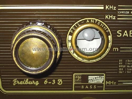
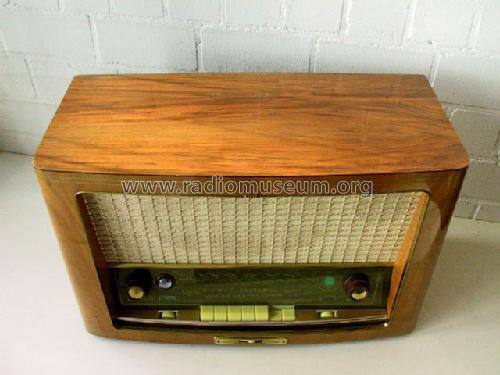
Recently I have bought a SABA Freiburg 6 with green dial.
I have noticed before that SABA has extended this variation to all the 1956 model range.
After 1956 SABA never user this dial again.
I wanna ask if someone as more information about this.
I really like to know more about this.
Francisco Martins, 14.Mar.25
Wo finde ich Technische Unterlagen fur ein Saba 6-3D in Englischer Sprache? Abgleich usw.
George Guma, 03.Jul.09
ich bin gerade dabei meinen 6-3D elektrisch zu restaurieren. Gerade habe ich die Spulen des Motorsuchlaufes durchgemessen. Je zwei gegenüber liegende Spulen haben 1,02 kOhm bzw. 0,78 kOhm.
Ist 0.7 kOhm noch in Ordnung ? Ich habe hier im Forum nur Angaben gefunden, daß alle Spulen um die 1kOhm haben sollten.
Wer kann hierzu etwas sagen ?
Viele Grüße
Joachim Herzig
Joachim Herzig † 10.2.19, 17.May.09
Ich suche für meinen Saba Freiburg 6-3D eine intakte Skalenscheibe sowie die passenden Lautsprecher, als Satz oder gerne auch einzeln. Des weiteren suche ich einen Satz Tastenköpfe für dieses Radio.
Vielen Dank
Joachim Herzig
Joachim Herzig † 10.2.19, 29.Mar.09
Guten Abend!
Mein neuester Zugang ist ein Freiburg 6 3D in äußerlich passablen Zustand und einen mechanischen Defekt im Bereich der Skalenseil-Umlenkung. Die erste Sichtprüfung ergab keinen Anlass zur Sorge oder sofortigen Reparaturmaßnahmen. Lt. Vorbesitzer sollte das Gerät bei manueller Senderabstimmung auch klar und laut empfangen. Diese Aussage fand ich bestätigt. Um mich mit der Skalenseilführung besser beschäftigen zu können wurde das Chassis ausgebaut u. vorsichtig gereinigt. Hierbei viel mir ein ganz offensichtlich durchgebrannter 100 Ohm Widerstand in der Gegentakt-Endstufe auf. Nach dem Schaltbild zu diesem Gerät handelt es sich um den Widerstand für G2 der einen EL84.

Ich habe diesen Widerstand ersetzt, aber nicht wirklich einen Grund für das Durchbrennen erkennen können. Der Widerstand war nicht nur unterbrochen sondern regelrecht geschwärzt.
Jetzt treten beim Betrieb des Gerätes starke Verzerrungen auf, besonders deutlich werden sie bei Anheben der Bässe. Aus dem Schaltbild kann ich zunächst keinen Grund erkennen, weshalb der Widerstand so hoch belastet wurde/wird noch warum nach dem Ersetzen Verzerrungen auftreten - außer ein Fehler in der EL84 selbst?
Wer kann helfen?
Axel Harten.
Axel Harten, 02.Jun.07
Werner Hauf, 11.Aug.06
Reparaturmaßnahmen zur SABA Automatic Steuerung
Eike Grund, 19.May.06
Mit freundlichen Grüßen
Marc Goeritz
Marc Goeritz, 14.Apr.06