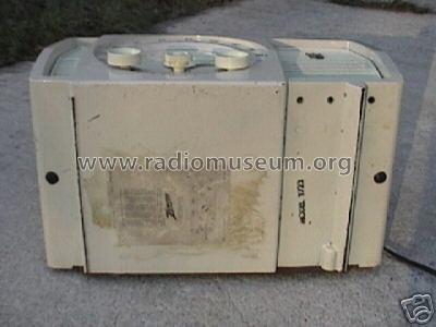
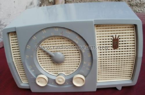
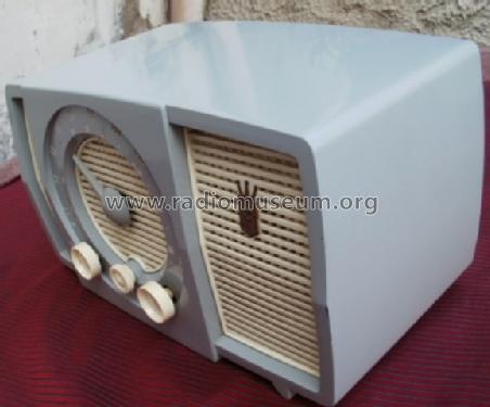
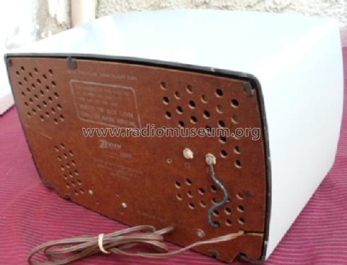
Y723 Ch= 7Y04
Zenith Radio Corp.; Chicago, IL
- Pays
- Etats-Unis
- Fabricant / Marque
- Zenith Radio Corp.; Chicago, IL
- Année
- 1956 ?
- Catégorie
- Radio - ou tuner d'après la guerre 1939-45
- Radiomuseum.org ID
- 73610
-
- alternative name: Chicago Radio Lab


RECONSTRUCTED LABEL
Cliquez sur la vignette du schéma pour le demander en tant que document gratuit.
- No. de tubes
- 7
- Principe général
- Super hétérodyne (en général)
- Gammes d'ondes
- PO et FM
- Tension / type courant
- Appareil tous courants (CA / CC)
- Haut-parleur
- HP dynamique à aimant permanent + bobine mobile
- Matière
- Plastique moderne (pas de bakélite, ni de catalin)
- De Radiomuseum.org
- Modèle: Y723 Ch= 7Y04 - Zenith Radio Corp.; Chicago,
- Forme
- Modèle de table générique
- Remarques
-
Sam´s 338-11. Beitmans Most Often Needed 1956 Radio Servicing Information. Page 182 shows probably the correct tubes for this model. See the schematic here. There is no 6BJ6 tube used there - but we showed it originally (for some reason ...). May be that two variants exist? Who can tell us?
- Auteur
- Modèle crée par Konrad Birkner † 12.08.2014. Voir les propositions de modification pour les contributeurs supplémentaires.
- D'autres Modèles
-
Vous pourrez trouver sous ce lien 4519 modèles d'appareils, 4111 avec des images et 3656 avec des schémas.
Tous les appareils de Zenith Radio Corp.; Chicago, IL
Collections
Le modèle Y723 fait partie des collections des membres suivants.
Contributions du forum pour ce modèle: Zenith Radio Corp.;: Y723 Ch= 7Y04
Discussions: 1 | Publications: 2
Fellow Radiophiles,
Years ago, I found with my Software Defined Radio SDR-Play, that all my local (Massachusetts USA) AM music stations broadcast with 10kHz audio bandwidth, but there are no modern radios with more than the standard 5kHz AM audio bandwidth. Most American tube radios hardly exceed a 2kHz bandwidth that is severely limited by their undercoupled IF transformers. There is still one station in my area, WJIB in Cambridge Massachussets, that even broadcasts its Oldies Music in AM C-QUAM Stereo at 740kHz. Follow the link for several posts on AM and C-QUAM stereo by Semir Nouri. The following screenshot was taken in the evening of November 7th 2016 around 11pm. Note how the spectrum is practically filled with AM carrier spikes every 10kHz. In Europe, the AM band station pitch is 9kHz and there are currently far fewer AM stations than FM stations. The upper-left panel shows the local station WLLH at 1400kHz with its usual music program. Note how the sidebands fill out the +/-10kHz spectrum around the 1400kHz carrier. I am happy to say that the AM spectrum in the USA is still full of stations, although the majority are for talk and news only.

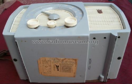
I want to try modifying and adjusting a conventional American AM tube radio for mono AM High Fidelity (HiFi) reception. My fellow radio collector Tom Kelly was very kind to give me a Zenith model Y723 AM/FM radio from circa 1956 in original unrestored condition. After examining its schematic diagram I found it interesting enough and with the potential to try the AM HiFi modifications.
With this HiFi modification we will appreciate the existing design and come up with the necessary improvements.
Click any picture in this post to enlarge.


 The scope of the modifications included widening the bandwidth in the AM RF and IF path to accomodate +/-10kHz around the AM carrier, widening the audio amplifier bandwidth to 10kHz and resolve distortion issues in the AM detector and Automatic Gain Control AGC circuit. In order to overcome the limitations of the fidelity of the internal round 4"speaker, I added a phone jack for an external speaker, which reconnects the internal speaker when the external speaker is unplugged from the radio.
My external speaker is an Optimus PRO-X88AV Radio Shack cat# 40-2085. This is a two-way speaker with a wide pattern tweeter and a 5" long throw woofer in a ported aluminum enclosure. Aside from a resonant peak around 100Hz, this speaker sounds pretty nice. The resonant peak is reduced with the port plugged with a cork for simple acoustic suspension without bass reflex. But this is a matter of taste.
The 4" speaker in the Zenith is the weakest point in the fidelity of this radio. Contemporary European radios, like even the small 3-tube AM-FM Grundig model 80U from 1955 with it's very nice sounding 5.5"x3.5" (14cmx9cm) oval speaker, usually sounded much better. This may well be what made European tube radios of the 1950's and 1960' famous for their sound quality.
 European Hi-Fi AM tube radios of the 1950's and 1960's also included 9kHz audio notch filters to eliminate the 9kHz whistle of the adjacent channel carrier. The plot shows the 9kHz notch for two tone settings in the Grundig 396W from 1950. Note the degradation of the treble response with the flatter tone setting. The following German language page shows a range of implementations of the 9kHz filter (click the country flags at the top of the page to read the post translated into other languages). I did not bother including a 10kHz filter as my primary transmitter was my own AM HiFi Tomato Can Transmitter, which was closely coupled to the radio to overwhelm any external sources of noise. With this strong signal, the AGC control voltage in the radio goes below -10V and runs the radio at very low RF/IF gain, which also greatly reduces any chance for adjacent channel 10kHz whistles. In practice, I never noticed any 10kHz whistles around my local stations. I made sure that the effect was possible to hear by running an RF generator 10kHz above and below the carrier of a local station and verified that a 10kHz whistle could be heard after the HiFi modifications. Both the local station frequency, 1000kHz for example, and the generator at 990kHz or 1010kHz would have to be present without retuning to confirm the >20kHz BW in the RF/IF path. But first, I had to solve the repair issues.
Repair of exposed silver-mica capacitors in the IF cans
 The only problems with the radio were the exposed silver-mica capacitor disks that resonate with the coils inside the IF cans. The capacitor plates are a deposited thick film of silver paste on the mica disk. These caps tend to fail over time. The plates are pressure contacted with metal pads inside the IF cans. Over time, the silver paste has sometimes cratered under the pads, that just rest on on them, thus loosing contact intermittently or permanently. The silver paste may have simply partially or totally evaporated/oxidized. Most radios with these capacitors have at least one failed silver mica capacitor disk. This process of loss of the conductive silver paste is often referred to as "silver mica disease" by American radio collectors.
The symptoms are easy to spot, because the loss of capacitance detunes the IF tank and greatly reduces radio sensitivity. The bigger problem is when the defect is an intermittent contact. One way to deal with the intermittent contact problem is to replace all of these silver mica disc caps, but it is quite a lot of work to take apart all 6 IF cans. I chose to replace only the caps in the 4 IF cans that showed intermittence while I played the radio for long periods of time. I also like to preserve the original condition of the radio as much as possible.
4 of the 6 silver paste mica disc caps and their transfomers with measured C and L

The figure above right shows the first AM IF transformer with the phenolic wafers partially separated to show the silver-mica disc cap and the clipped rounded metal terminal pads that rest on the conductive silver paste. The bits of metal pad near the disks had to be cut out of the terminals to avoid short-circuiting the terminals when the mica disk is removed. The figure above shows the silver-mica caps for the 1st, 2nd and 3rd IF transformers and for the FM discriminator. The terminals are viewed from below in the drawings. The capacitors were measured with my B&K 820 capacitance meter. The inductors were measured with my Rhode&Schwartz BN6100 inductance meter. It is best to measure the inductors with the original factory alignment, before any new alignment is done.
The capacitors may be part of the IF tanks or just for the low pass detection filter seen at terminals 3 and 6 of the AM-IF3 transformer can. Each can has only one mica disk with several capacitors made from several conductive islands that are individually contacted. More than one conductive plate on one side of the mica may share a single conductive plate on the other side. These caps have a common terminal connection for the shared plate. The capacitances are always measured between the top and bottom conductive paste plates.
 The values of the capacitors were not specified in the schematic diagram, so I had to measure them. I also measured the inductance of all the windings to be sure all values made sense.
Resonant Frequency=1/sqrt(L*C*2*Pi).
Because there was no sign of evaporation around the edges of the silver paste, the value of the caps should be close to the original value. The value of each of the capacitors on the mica disk varied from around 20pF to 200pF.
I used COG ceramic and silver mica molded capacitors as the replacement. The new cap values were within 10% of the measured value, which is within the range that can be accommodated during the IF alignment. I placed the replacement caps inside the first IF transformer can, but decided later to wire the capacitors outside the transformer cans.
A schematic design with potential for AM HiFi modifcations
Modification of the 455kHz AM IF Bandwidth from less than +/-5kHz to +/-10kHz
This radio has three FM-IF-only transformer cans and two AM-IF-only transformer cans. The middle IF stage uses one can with one AM tank and one FM tank. All IF cans have no more than 2 coils per can. Typical AM HiFi receivers have overcoupled AM IF transformers so that the 10kHz bandwidth is a characteristic of each transformer. The only single tuned tank is usually the loop antenna, which is centered in the IF response and can fill-in the dip at the center of the IF response. In this radio, I used the two single tank responses of the loop antenna and 2nd IF tank, combined with two overcoupled responses to obtain a flat response like the example in curve "c" on the plot on the right.
The left graph shows various levels of coupling between tanks with little change in gain. The right graph shows the cascade of a double-peaked overcoupled and and single peak undercoupled stage to produce the flat curve. The flat curve is the result of multiplying the other two curves together.


These two graphs came from pages 211 and 224 in the excellent book "Vacuum Tube Amplifiers" by Walley and Waldman 1948. The book is available freely in pdf form. Do a web search for "Vacuum-Tube-Amplifiers-Valley-Wallman-1948-761-pages.pdf". You will find a rigorous and very extensive exploration of this topic.
Measured Overcoupled Response of a Single AM IF Transformer
I used an HP3314a to sweep the IF frequency around 455kHz, by +/-50kHz, to verify the bandwidth curve of each stage. The sweep was necessary because I was going to widen these curves for +/-10kHz bandwidth and had to monitor the new frequency response profile. Once the redesign is finished, the proper alignment procedure is to load one of the windings at the primary or secondary with a 10KΩ so that the overcoupling disappears due to lowered Q and you get a very clear peak for both secondary and primary. This is standard procedure for the alignment of any AM or FM IF transformers with over-coupled double peaks.
Each IF transformer response was measured individually with the sweep signal driving the grid input of the IF stage, and the measurement was done at the secondary with a low capacitance (12pF//10MegΩ) 10x scope probe. The scope probe detunes the tank, but it is still useful to see the frequency response shape and to experiment with over-coupling amounts. The tank needs to be retuned under the probe load to observe the correct response. In the final alignment all measurements are done after detection, so there is no detuning of the tanks by the scope probe.
This radio had the further challenge that the second IF stage used a single tuned circuit that could not be overcoupled for the 20kHz IF BW. The original narrow 4.8kHz IF bandwidth would produce a sharp resonance at the 455kHz center IF frequency, which would sound like a bass-midrange boost up to 2.4kHz.
The two AM IF transformers, at the 1st IF and the 3rd IF, were originally under-coupled and had a narrow 13kHz bandwidth. The net bandwidth over the 3 IF stages was 7kHz. The detected audio bandwidth is half the detected IF, bandwidth, so 6.5kHz and 3.5kHz, respectively. Keep in mind that even an undercoupled transformer has a wider bandwidth than the bandwidth of the individual tanks.
 Overcoupling for full +/-10kHz is easy to do for these transformers with small <10pF ceramic COG caps bridging the plate connection of the primary to the output pin of the secondary. This is what I did with 8pF bridging the 1st AM IF transformer and 6pF bridging the 3rd AM IF transformer. These bridge caps are about 6% of the value of the caps at each tank. This gives very strong overcoupling with the Q of each tank around 35. The added strong over-coupling is necessary to create two strong peaks at +/-24kHz that when combined with the center peak of the single tank of the 2nd IF tank and the single center peak of the AM loop antenna produces a pretty flat +/-10kHz RF/IF bandwidth.
Small Signal AC Simulation of the entire Signal Chain from Loop Antenna to AM Detector
The following small signal AC simulation in LTSpice freeware was modeled from measurements taken from all the IF tanks and loop antenna. The tubes were modelled with the published small signal parameters gm, Rplate and parasitic capacitances. The transconductance of the 12AT7 Mixer is the measured conversion transconductance Sc, which is impressively high at 1.4mS. This being a linear simulation without the possibility for non-linear frequency conversion I resonated the loop antenna at the 455kHz IF frequency. The simulations results on the right show the response to the AM detector from 4 points along the signal chain: from the external RF signal at the top, from 12AT7 mixer grid, from the 12BA6 IF1 grid and from the 19HS6 IF2 grid at the bottom panel.
One might think that simply stagger-tuning each undercoupled IF tank will wield the desired +/-10kHz IF bandwidth. Although this is possible, it is at great cost to gain because the slopes of each stage is quite steep. The illustration above and the simulation below show that over-coupling does not attenuate the signal.
The blue curves show the overcoupled response and the red curves show the original undercoupled response. But the IF2 tank in the simulations is the redesigned version with 27kHz BW; not the original with 4.8kHz BW. So the original IF bandwidth was even narrower than the 7.1kHz shown here.

Redesign of the AM/FM IF2 tank
I redesigned the IF2 tank to get more bandwidth than with the original design. See the original and modified versions below on the two left panels. Note that the plate load for the IF2 stage is the FM IF tank, which is used for both AM and FM. In the FM case this poses little loss, but in the AM case the FM tank is the equivalent of a low Z tap in series with the AM tank, which keeps the original AM gain limited to 9.5dB. This is an odd design with a 4.8kHz bandwidth peak next to a sharp notch, as shown in the following upper panel to the right. Also note that the original tank provides little rejection below 455kHz.
The simulation schematic takes input at the 12BA6 grid and gives the result at the grid of the following stage. The 12BA6 gm and grid/plate parasitic capacitance are included. My redesign of the combined AM/FM tank pair gives still the same modest gain of only 10dB, but with a much wider 27kHz bandwidth. The FM gain dropped from 35.6dB to 29.5dB. This 6dB FM gain loss was made up in the following 2nd FM IF stage by replacing the original 12BA6 (gm=4.4mS) with a 19HS6 (gm=9.5mS) sharp cutoff pentode. This higher gain also benefits the AM IF by the same amount.
The resistors in parallel with the inductors model the measured Q and are not explicit resistors in the design. The IF2 tanks are shaded in blue.
The blue curves show the response at the plate/filter-input and the red curves show the output of the filter, which drives the grid of the IF3 stage.

Measured RF/IF response after modifications
The top row of the following six scope photos shows the detected RF/IF response at the top of the volume control to +/-50kHz sweeps around the 455kHz center frequency on the top row. The second row shows +/-50Khz sweeps around three RF frequencies at 610kHz, 970kHz and 1470kHz. The generator is first fed to the the second AM IF stage grid input to show the IF3 transformer response. Then the generator injection point is moved back one stage at a time toward the loop antenna. The loop antenna picks up the signal from a small loop that is driven by the generator with sufficient distance from the loop antenna to avoid affecting its response. The AGC voltage was forced externally to -5V and the generator amplitude was adjusted to give a usable response on the scope.
These sweeps correspond to the simulations above and are in reasonable agreement. The measured loop response beeing flatter than simulation means that the real loop antenna Q was a little lower than what I simulated. The vertical cursor lines are at +/-10kHz.


 This photo shows the test loop I used to transmit the AM band signal into the loop antenna. The loop has a tuning capacitor in parallel with the loop that can be use to tune for peak response if driven from a high impedance >10kΩ. But here the loop was driven with a 50Ω impedance from the generator to ensure a flat response. When driven with the 50Ω impedance it makes it much less likely to detune the loop antenna in the radio when placed near it.
This little 4 inch diameter 240uH coil is of modern construction and was bough online ten years ago. The build quality is very high and so is the measured Q=95 at 1MHz.
Typical IF transformers in AM HiFi designs
If this radio had been designed for AM HiFi it would have made sense to have only overcoupled IF transformers without any single IF tanks, like in the 2nd stage of this Zenith, so that each transformer would not have to be so radically overcoupled and the response of the front end loop antenna would combine to get a flat combined response.
 The over-coupling of the IF transformers in AM HiFi sets is usually done magnetically with an extra small winding in series with the secondary on the AC ground side, that is placed very closely to the primary.
The example on the right has a mechanically adjustable winding that is brought closer to the primary winding for overcoupling or pulled away for undercoupling. The mechanical control is shared with the treble knob. In some designs this winding is switched in and out for narrow or wide IF bandwidth.
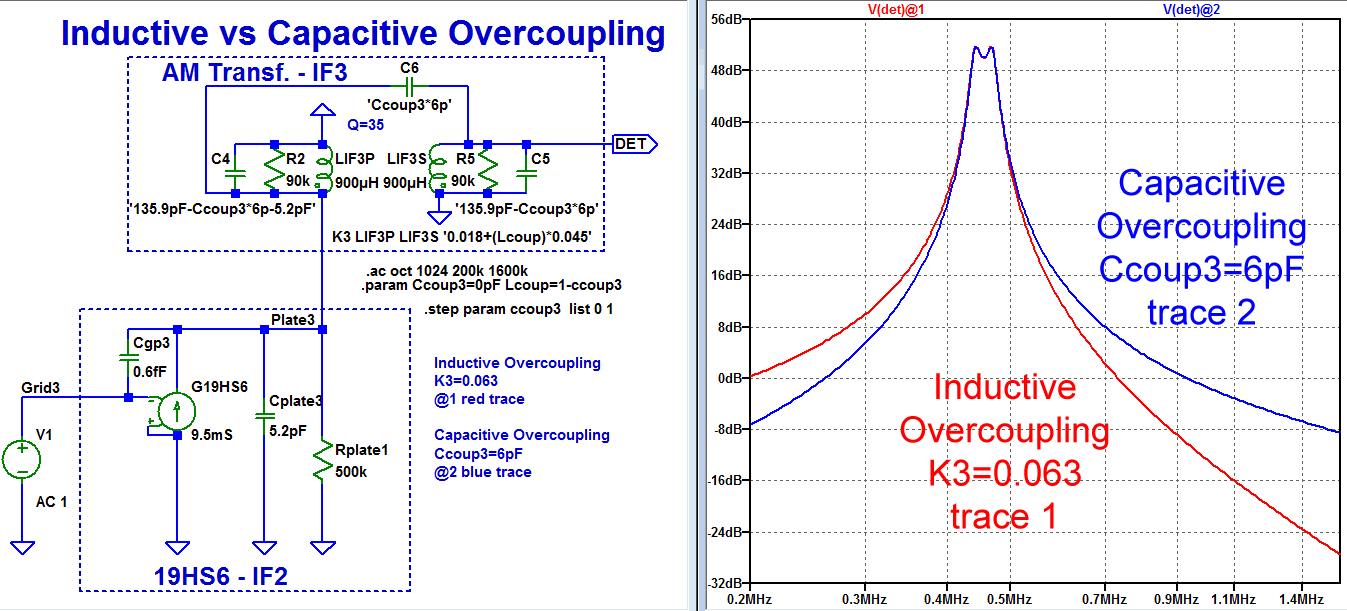
Inductive vs Capacitive Overcoupling
I used capacitive over-coupling bridging the primary and secondary of the IF transformers because adding the extra coil would have been too difficult. Capacitive overcoupling has the disadvantage of limiting the high frequency rejection at the image frequencies which lie between 530kHz+455kHz=985kHz and 1710kHz+455kHz=2165kHz.
This simulation compares inductive overcoupling in the red trace with capacitive overcoupling in the blue trace. Notice how the capacitively overcoupled filter rejection at 985kHz is 11dB less than for the inductively overcoupled case. With the two capacitively overcoupled transformers in my modifications the rejection at 985kHz is on the order of 22dB poorer than with inductive overcoupling. This has not posed any problems in practice. The single tanks of the loop antenna and the IF2 stage help the image frequency rejection.
RF front end and Mixer stage
This radio has an interesting front end design that distinguishes it from more conventional AM-FM tube sets. This design was typical in Zenith sets from the 1949 Zenith model 7H920 to the 1960 Zenith model SFD2570. There were some variations along the way, with this last model using 6V heater tubes.
 The FM section includes a broadly fixed tuned RF preamp that uses the VHF Pentode 6BJ6 (in the R-723 version).This pentode was designed for higher input impedance (3.6kΩ at 100MHz, click the App note on right) than the older 12BA6 (1.7kΩ at 100Mhz, click Input Admittance on the right). The higher input impedance makes it possible to transform the typical 300Ω antenna impedance into 3.6kΩ with a turns ratio of sqrt(3600/300)=3.5x. This increased turns ratio drives the 6BJ6 with 3dB more signal voltage than is possible with the 12BA6, which improves the Signal-to-Noise Ratio SNR in the FM band by 3dB. The AM section has no RF preamp, with the internal loop antenna driving the grid of the 12AT7 additive triode mixer stage directly.
 The AM and FM frequency converters share the 12AT7 dual VHF triode with one triode working as aditive AM-FM mixer and the other triode as AM-FM local oscillator. This is a departure from conventional AM-FM sets that usually use a separate pentagrid converter for AM, like the 12BE6 or ECH81, which may get switched around to work the first IF stage in FM mode.
Mixer with AVC control
12AT7 Mixer Time Domain Simulation with AVC Sweep (Click to enlarge)
The most unusual part of this circuit is the direct application of half of the AGC control voltage in AM mode to the 12AT7 aditive mixer triode grid pin2. This AM-AVC approach was also used in the Grundig line of AM-FM 3-tube sets from 1955 to 1965 starting with the Grundig model 80U (click the country flags at the top of the page to read the post translated to other languages). There is also an English translation of an introductory article to this radio in volume 20 of Funkshaw magazine from 1955. The 12AT7 mixer grid pin2 also serves as the RF input for both bands. The local FM oscillator injects into the aditive mixer grid pin2 with a 0.68pF cap from the 12AT7 Local Oscillator (LO) plate pin6. The injected voltage was measured with a Germanium diode as 2Vp-p. The AM LO triode injects from its cathode pin8 through a shared step-down tank coil into the AM additive mixer cathode pin3. The injected level at the mixer cathode is 4Vp-p
The full AVC voltage drives the 12BA6 remote cutoff pentode in the first AM IF stage. In this arrangement, half of the AVC bias voltage in AM mode is added into the mixer grid together with the RF signal. But this is a sharp cutoff triode. A sharp cutoff triode in an amplifier stage under AGC control and with the usual fixed DC plate voltage would distort as signals increase and the AVC voltage at the grid gets more negative toward cutoff of the triode.
 The oscillation amplitude of 4Vp-p volts injected into the mixer cathode spreads out the cutoff point of the mixer triode for RF signals. With the 90VDC supply voltage at the mixer plate, the grid cutoff voltage would be approximately 90V/mu=90V/52=-1.7V. In the simulation shown above, the 4Vp-p oscillation injection at the cathode extends a -2.5V cutoff point gradually to -5.4V with the RF input set to 2Vp-p. See the simulation above.

 The onset of measured visible distortion (<5%) occurred when the RF at the 12AT7 mixer input pin2 was 2Vp-p with 95% triangle modulation at 220Hz and VAGC bias at the mixer grid was -4.2V. This corresponds to a VAGC bias of -8.4V at the IF2 pentode control grid. The detected voltage at the top of the pot is -9.8Vdc.
The second scope photo shows the RF signal into the grid increased to 3.4p-p. Note the gentle second order distortion that occurs as the mixer gets overdriven. Note also the slight drop in gain as shown by the detected triangle wave shrinking into the RF level, as compared to the first photo.
Getting more than 2Vp-p of RF at the loop antenna, which ties directly to the mixer grid is very difficult to get in practice. The strongest station in my area radiates 50kW and is 5miles (~8km) way from my house. The radio AVC voltage at the IF2 pentode is only -5V. This corresponds to 60mVp-p at the loop antenna. You would need to be under a 1/4mile from the transmitter to get a voltage approaching 2Vp-p at the loop antenna.
The triode mixer has a very gradual cutoff down to -5.4V, but it does not extend as far as the 12BA6 remote cutoff pentode, which extends down to -30V as seen in the graph below. The good operation of the triode mixer is made possible by driving the mixer stage with only half of the AGC voltage that is applied to the remote cutoff pentode 12BA6 at first AM-IF stage. This AGC technique was used in the aforementioned Grundig model 80U. The AVC in this Grundig radio is shared directly without attenuation between the triode mixer grid (ECC85) and the IF pentode (EBF90). This is made possible by the fact that its triode mixer operates with 200Vdc which is over twice the 90V supply voltage of the Zenith Y723. With double the plate supply, the triode cutoff point of the triode also doubles.
High Conversion Transconductance Sc
The AM band mixer conversion transconductance Sc was measured to be 1.4mS from the grid to the plate of the 12AT7 mixer. This is much better than Sc=475uS with 12BE6 frequency converter or Sc=775uS for the ECH81 frequency converter. Both of these tubes were the industry standard in the US and Europe, respectively. The higher Sc gives inherently lower noise than with these two heptodes. There is also no partition noise between screen grid and plate currents, that is inherent to heptodes. the reduced noise is particularly useful for FM.
RF/IF signal measurement technique
The RF/IF signal measurement technique uses a calibrated RF generator and a DC voltmeter to inject a calibrated RF/IF signal level that corresponds to a chosen DC level at the AGC voltage. This way there is no loading or detuning by scope probes. With an accurate RF attenuator, as with my HP3314A generator, accuracy approaching 1% is easy to get. The following procedure was used to measure Sc as well as all RF/IF signal levels and gains.
Measurement of the Conversion Transconductance Sc:
- Inject a few mV of 1MHz AC-coupled RF with 20nF into the mixer input grid pin 2 of 12AT7 and tune the radio for a maximum level at the AGC voltage.
- Adjust the RF level to obtain VAGC=-1.00VDC at the AGC bypass cap C17=10nF, which sets the DC bias for the control grid of the 12BA6 IF2 pentode. VAGC=-1.00V was chosen because this is just above the VAGC=-0.5V which is obtained with zero signal from the generator, so that there is little AGC action. The AGC voltage at the mixer input is half of the VAGC at the IF1 pentode.
- Record the RF level of the generator for VAGC=-1.00V, which was 0.68mVp-p.
- Increase the generator output to 1.36mVp-p. This increases the VAGC, to around -1.5V
- Measurement of mixer load resistance: Load the first IF tank with a resistor that reduces the VAGC back down to -1.00VDC. The tank connection is between the mixer plate tap at the IF transformer pin 3 and the HV supply at pin4 of the same IF transformer.
- The value of resistance that satisfied step 5 was 3.3kΩ. This value of resistance matches the impedance at the triode mixer plate. because it is the value that cuts the RF signal in half.
- Change the generator frequency to 455kHz and AC-couple it to the mixer plate 12AT7 pin1.
- Find the generator amplitude that again gives VAGC=-1.00V. In this case, the value was 3.14mVp-p. This means a mixer conversion voltage gain from grid to plate of 3.14/0.68=4.6X.
- The transconductance Sc=4.6/3.3kΩ=1.4mS
- A similar procedure forcing 455kHz at the top of the first IF tank at pin7 of the transformer to get VAGC=-1V finds that the required level is 10.6mVp-p. This gives a net voltage gain from mixer grid to the top of the first IF tank of 10.6/0.68mV=15.6x
AGC control with remote cut-off tubes
 Remote cut-off pentodes like the 12BA6 have a very gradual cutoff characteristic up to -30V with Vg2=+100V. The remote cutoff actually reduces the level of gain control vs grid bias voltage. For example, the plot shows -10V reduces gm from 4.4mS to 300uS, a -23dB gain reduction, but -20V only reduces the gm to 70uS, a -12.6dB gain reduction.
This gain control is very gradual, as compared to the extreme gain control that is possible the sharp cut-off version 12AU6. But sharp cutoff 12AU6 would, distort badly with strong signals near its -4.2V cutoff. The larger the signal, the more negative the AGC voltage. The remote cutoff characteristic is a compromise between keeping distortion low at the largest signals, while maintaining usable gain control. The dominant criterion in the design of a remote cut-off pentode is to minimize distortion as the signal into the grid increases. This necessarily means less gain control as the AVC bias gets more negative.
In the end, it is nearly impossible to overdrive a radio with remote cutoff pentodes like the 12BA6, but the variation in detected audio vs signal strength, while reduced from the signal variation at the antenna, still remains wide. In this particular set, with the 12AT7 mixer and the first 12BA6 AM-IF stage under AGC control, a measured 70dB variation (680uVp-p to 2Vp-p with 100% modulation into the 12AT7 grid pin 2) in input signal strength still produces a 26dB variation in detected audio and incremental AGC voltage (-0.5VDC to -10VDC). Distortion was monitored to be acceptably low during this signal range with up to 2Vp-p into the mixer grid.
So, for low distortion, the signal at the remote cutoff grid must always be much smaller than the AGC voltage bias at the same grid. That is why, in order to control the gain with a 2Vp-p input, a -10.5VDC AGC bias was needed. At this level, as we will see, the Triode mixer gain drops to around 1 (see measured graph below on the second row left) and the 2Vp-p signal level at the remote cutoff grid of the 12BA6 is much smaller than the VAGC=-10.5V at its remote cutoff input grid.
The remote cutoff characteristic poses the problem in the AGC control design to avoid distortion in a HiFi design if the last IF stage is under full AGC control. If the signal were strong enough to cause the last AM-IF stage gain to approach a gain of 1, the magnitude of the signal into the grid would be comparable to the detected AGC bias voltage, thus causing a lot of distortion.
One common solution to this problem is to set the last AM-IF stage with high gain under fixed bias, or under reduced AGC control. This way, the detected AGC voltage is always much larger than the signal at the remote cutoff grid under AGC control. In this set, the second AM-IF stage with the upgraded higher gm 19HS6 is run with a fixed gain of 220x and a -1V cathode bias with a bypassed 100Ω cathode resistor.
Measured RF/IF signals and stage gains vs. AVC in the Horizontal Axis
click the plots to enlarge
- First row left compares AVC voltage levels (solid curve) to the AC RF/IF signals (dash curve) at the 12AT7 mixer grid (red) and the 12BA6 grid (blue) in the IF1 stage. The AC signals are always much smaller than the AVC dc signals on the same grid. In the worst case, VAVC=-10.5Vdc at the pentode grid corresponds to a little over 1Vp-p at the same grid. For the mixer, VAVC/2=-5.2V corresponds to a little over 1Vp-p. Also note that the straight red dashed line showing the input signal in Vp-p is a fairly straight line, thus showing a nearly log characteristic with respect to the developed AVC voltage. This near log characteristic is an improvement over the 12BA6 curve alone and is the combination of the mixer and IF1 AVC curves.
- First row center shows the Loop antenna signal level in the red trace, the AVC signal on the horizontal axis is also in the black trace. The signal at the detector anode is the blue trace and is truncated to a maximum of 20Vp-p, because that is the maximum that the generator could output. The overall AM RF/IF signal gain from the loop antenna to the detector anode is shown in the solid magenta trace. The dashed magenta trace shows the signal gain from loop antenna to AVC detector. Note that the gain only starts to get reduced when VAVC<-2V. This provides and AGC delay up to VAVC=-2V. You also notice a slight decrease in gain below VAVC=-1V. This is due to the slight loading by the 12BA6 grid in the first IF stage. Until there is enough negative bias. The grid impedance of the 12BA6 was measured around 220kΩ with zero signal present. This impedance rises dramatically as soon as the grid bias gets below the contact potential around -1V.
- First row right shows the gain (attenuation) in magenta in the 19T8 AVC detector from the IF signal at the anode in red to the detected AVC in red. The attenuation is lowest around 0.25 for larger signals and drops significantly for smaller signals to the right.


- Second row left shows the 12AT7 mixer RF input in the red trace, the mixer IF output in the blue trace and the mixer gain the magenta trace. The mixer VAVC/2 is in the black trace. The mixer gain varies from 10 to 1 without distortion. Note how there is no gain variation in the magenta trace until VAVC reaches -3V. This shows that the mixer has a built-in AVC delay of VAVC/2=-1.5V.
- Second row middle shows the 12BA6 IF1 grid input in the red trace and its output at the 19HS6 grid input in the following IF3 stage in blue. The VAVC trace from the horizontal axis is repeated in black. The curvature of the black trace comes from the vertical log scale. The magenta trace shows the IF1 stage gain. Note how it varies from a maximum of 3.7x on the right to a gain of 1 for VAVC=-3.5V and down to a steep attenuation of 0.14x when VAVC=-10.5V
- Second row right shows the the 19HS6 IF2 grid input in the red trace and its output in the detector anode in the blue trace. The trace is truncated because the generator could not replicate detector anode levels above 20Vp-p. The magenta trace is the ratio of the red and blue traces and shows a fixed gain of 220x


The fixed, relatively high gain of the last AM-IF stage is a standard practice in AM HiFi receiver design. Some of these Hi-Fi am sets get by with reduced AGC voltage at the last AM IF. If the gain of the last AM IF stage were under full AGC control and its gain dropped near 1 with strong signals, then the signal into its grid and the AVC dc voltage into its grid would be comparable, which would produce a lot a distortion. The AVC voltage must always be much larger than the signal at the same grid, in order to get low distortion
AM HiFi tuners like the Heathkit AJ-41, AJ-10 and BC1A have reduced AVC voltage control at the last IF stage. These radios also use voltage doubling AM detectors to supplement the IF stage gain with a detector gain of 2x that can't be reduced by AGC control. The schematic below is the AM tuner section of the AJ-41. Note that both 6BA6 RF and IF tubes have a bypassed cathode resistor to elevate the cathodes about 1V. This is necessary because otherwise the 1N34 detected AVC would be at 0V with zero signal while the 6BA6 grids would sit around -1V if the cathodes were grounded and would be loaded by the AVC circuit filter resistors. Note also the selectable overcoupling switch at the first IF transformer for wide/narrow bandwidth. This switch is cleverly arranged so that the winding inductance for the small coil is always connected in series with the secondary tank to eliminate detuning the secondary between narrow and wide modes. In the configuration shown, the extra coil increases coupling for wideband and actively decreases coupling in narrow band. The bridged Pi CLC filter on the far right blocks the potential 10kHz whiste from adjacent channels.

Tube upgrades: 6BJ6, 19HS6
The original 2nd IF tube was the 12BA6 (gm=4.4mS) running with fixed bias, with a fixed gain of 108x. I replaced it with the 19HS6 (gm=9.5mS) to double the AM and FM IF gain. I used the sharp cutoff 19HS6, because this stage is run at fixed gain. The remote cutoff version is the 19HR6 (gm=8.5mS). This tube can serve as an upgrade in an AM set with a 12BA6. The increase heater string voltage also helps the upgraded radio operate with the slightly higher 120VAC>117VAC from the modern mains.
The original tube lineup was 12BA6,12AT7,12BA6,12BA6,12AU6,19T8,35C5 which adds up to 117V. There was an option for the Zenith R-723 model version to replace the 12BA6 FM from end with the higher RF performance 6BJ6, which also reduced the heater string to 110.7V. Substituting the 12BA6 in the 2nd IF with the 19HS6 brought the heater string total back up to 117.1V.
Audio distortion improvements
In the effort of turning this radio into a HiFi set, I found three different distortion problems:
1. At low frequencies <50Hz due to AGC modulation
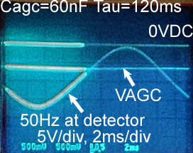
 The issue at low frequencies is that the AGC time constant was too fast at 20ms, such that at 50Hz, the RF/IF signal path was modulated by the AGC voltage following the 50Hz audio in real time, thus producing a 100Hz second harmonic. See the left photo. The solution was to increase the AGC time constant by 6x to 120mS by adding 0.047uF in parallel with the 0.01uF AGC filter capacitor. The photo on the right shows the cleaned up 50Hz distortion with the longer 120ms time constant. The second trace from the top in both photos is the AGC voltage and it is now pretty flat in the photo on the right. Now 50Hz sounds very nice on the external speaker.
2. At high frequencies >2kHz due to diagonal distortion

 The issue at higher audio frequencies >2kHz was the classic diagonal distortion that occurs when the load of an envelope detector is too light, such that the detector voltage can't follow the fastest dips in the envelope. On the oscilloscope, this looks like slew rate limitation on the inward slopes towards zero, but there is no problem on the downward (outward) envelope slope, that is driven directly by the forward biased detection diode. In forward bias the diode and tank circuit have about a ~50kΩ impedance, which is low, compared to the light ~450kΩ (1 MegΩ volume pot//AGC network//1MegΩ resistor) load to ground. This explains why the maximum upward slope should be 10x slower than the downward slope. The slew limitation is the diagonal distortion. It sounded nasty! The solution is very simple. I reduced the 190pF+100pF envelope filter caps to 39pf+47pF. These reduced caps in combination with two more stages of high frequency filtering in the audio amplifier still provide plenty of filtration of the 455kHz IF ripple.
3. With IF<1Vp-p at detector and high modulation levels.
All diode detectors have a minimum RF/IF signal amplitude that they can detect. Below this level the detectors become too linear and look like simple resistors. As the signal increases the diode has a square law V/I characteristic. This detects signals, but with distortion. Square law detection is still useful for speech or for morse code detection where the carrier amplitude just turns on and off. For low distortion audio detection, the characteristic must look more like an ideal diode. That is a very low fixed resistance in forward bias and an open circuit in reverse bias.
 I found that the lowest detectable IF carrier level produced around -250mVdc at the AM diode detector in the 19T8 tube. If the average carrier level is detected as -500mVdc, which is the case with a weak station, there is hard clipping of the top 20% of the detected audio. See the left scope photo. This is a fundamental characteristic of the 19T8. The average detected DC carrier level is visible in the quiet passages. I was very surprised that 20% of clipping was not very unpleasant. One reason may be that the harmonic content of the clipping is mostly 2nd order, which creates even harmonics one octave apart, that are not dissonant.

 Crystal detectors like the 1N34 detect levels down to 50mVp-p, where they start to look like square law devices. Below the Germanium diode thermal voltage Vt=26mV, the 1N34 becomes too linear to detect. Germanium detectors also have the advantage that their reverse leakage of a few μA helps to bias them to fully discharge the envelope filter capacitors and thus reduce the possibility of the diagonal distortion seen above. Their zero crossing impedance is around 10kΩ. This value decreases linearly in forward bias as a function of current and increases linearly in reverse bias as a function of the difference between current and the saturated current level Io. The photos show the triangle modulated transmitter RF and the detected triangle wave. The left photo has an average -100mV detected carrier level and shows square law detection (soft clipping) below -50mV. The right photo has a stronger signal with a detected carrier level at -600mV. There is no noticeable square law detection, except maybe at the positive peaks with nearly 100% modulation.

 The 1N34 crystal diode detects levels that are 10x smaller than the thermionic diode in the 19T8. The 19T8 could accomplish the same result as the 1N34 with 10X more IF gain to deliver with 10x more signal for detection. This is one of the fundamental reasons why RF or IF gain is always necessary before the detection diode. Note how these scope photos show excellent detection with detected carrier levels at -0.5VDC and -2VDC. The previous two photos with triangle modulation show that detection with the 1N34 remains reasonable down to -0.1VDC of detected carrier level. In practice, the detected noise between stations has an average around -100mV. So any station worth listening to, has at least -0.5VDC average detected level.
Modern stations broadcast with modulation levels up to 95% with special compressors like Optimod. The modulation levels in the 1950s, when this radio was designed, were much lower, not much beyond 50%. Compression was probably not used back then either. Our late RadioMuseum member and my good friend Prof. Rudolf Dietmar left an excellent and comprehensive post on the topic of HiFi AM receivers (This post is in German. Click on the country flag at the top of the post for translation to other languages). You should look up other posts by Prof. Rudolf. He left an amazing legacy of almost 2500 extremely well edited posts.

The schematic shows the modifications to the detector filter cap values and the addition of the 1N34 germanium crystal diode audio detector. It was necessary to retain to the 19T8 to detect the VAGC level because the 19T8 has -0.5V of contact potential self bias. This contact potential is comparable to the grid contact potential of the 12BA6 IF pentode and the 12AT7 mixer. When there is no signal present, the detected DC value from the 1N34 is 0V, which would tend to slightly forward bias the grids of the 12BA6 and 12AT7.
The Audio Amplifier
While we are addressing the audio issues, the bandwidth of the 35C5 power pentode stage was limited to 6kHz by the 0.01uF capacitor across the 2.5kΩ impedance of the output transformer primary. This capacitor prevents over-voltage spikes at the plate when a large negative spike is presented to the 35C5 input and the pentode cuts off, the energy stored in the leakage inductance of the output transformer is released, thus causing a huge high voltage spike at the plate. The 0.01uF cap soaks up these spikes and protects the pentode plate and output transformer primary from voltage spikes of hundreds of volts. Click the schematic and plot to enlarge.

The simple way to regain much of the audio bandwidth above 6kHz is to wire the capacitor between the unbypassed cathode and the plate of the 35C5 pentode. The 150Ω bias resistor at the 35C5 cathode and the cathode impedance 1/gm=1/5.8mS=172Ω split the current from the 0.01uF capacitor. This reduces the effective capacitance by half. I also further reduced the 10nF cap to 5nF. Now the power pentode stage bandwidth goes out to 10kHz.
The simulation schematic blocks above on the left show the output capacitor being moved from ground to the cathode. The top panel of the plot shows the simulated frequency response for the two cap values and connections with a simple 2.5K resistive plate load.
The simulation schematic blocks on the right show the full output stage with the 35C5 pentode, the output transformer and the internal 2.8Ω (DC resistance) speaker at top right and with external 8Ω (Optimus PRO-X88AV) speaker at the bottom right. I modeled the values in the schematic for the linear AC simulation with various frequency sweeps and measurements at the transformer output terminals with a speaker load, open load and with a short circuit load. The lower panel shows the response as measured at the speaker terminals and is not the acoustic response, which must be modeled from measured acoustic sweeps with a microphone.
The simulation is a fair representation of the linear AC response but it is not perfect. Note the resonant peak at 230Hz on the blue internal speaker trace. This reflects the acoustic resonance of the cabinet that makes the 4-inch speaker sound tinny. The high frequency resonant peak for the internal speaker is at 5.5kHz and for the external speaker it is at 10kHz.
Please keep in mind that this is only a simulation of the voltages present at the speaker terminals and not of speaker sound.
Measured Audio Response
The following 8 scope photos show a log audio sweep over 3 decades from 20Hz to 20kHz. 3 divisions per decade. Each division follows the sequence 20-43-92-200. The sweep duration is 1.8s. The audio sweep instrument is an HP3314A. The amplitude displayed on the scope is in linear scale, not in log scale as shown in the simulations above. The signal is modulated into the HiFi transmitter, transmitting at 750kHz. The eight photos show the signal chain response as follows:
- (first row)Scope probe (2V/div) at transmitter loop antenna, showing that is is perfectly flat to 10kHz.
- Scope probe (1V/div) at the top of the volume control with the response down to -8dB at 10kHz. This bandwidth is smaller than the RF/IF bandwidth shown above due to the envelope detector bandwidth limitation. The RF/IF sweep above was detected as a variable DC level that is not limited by the envelope detector bandwidth.
- Scope probe (1V/div) at the 19T8 triode grid shows a bass boost around 100Hz and a full 10kHz response. The response loss at 20Hz comes from the 0.01uF AC coupling cap to the grid.
- Scope probe (1V/div) at the 35C5 power pentode grid shows a slight improvement in the 20Hz response because of a lower setting at the volume control and the feedback network at the bottom terminal of the volume control pot.
- (second row) The scope probe (1V/div) is at the output transformer speaker terminals with a 3Ω resistive load. Compare with the speaker load response in 7. and 8.
- The scope probe (1V/div) is at the output transformer speaker terminals without a load The high frequency peaking around 3kHz comes from transformer resonance, which also overdrives the pentode, which produces the assymetric response.
- The scope probe (1V/div) is at the output transformer speaker terminals with the internal speaker as the load. The sharp cabinet/speaker resonance at 300Hz is prominent and gives the radio a very tinny sound.
- The scope probe (1V/div) is at the output transformer speaker terminals with the external speaker Optimus pro-X88AV. The bass resonant peak is at 130Hz. This also includes the response of any crossover networks in the speaker.
Click to enlarge


![]()
![]()
![]()
![]()
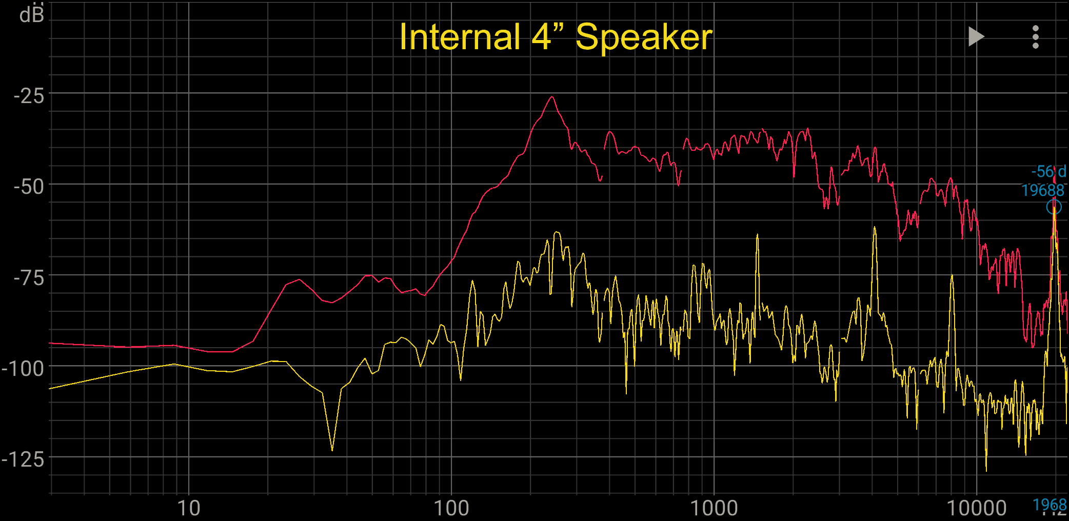
The overall audio response using my cell phone and the freeware Spectroid application for the Android OS. The shot on the left is with the internal speaker and the shot on the right is with the external Optimus speaker. Disregard the yellow trace, as it is the live trace following the 1.8s sweep. The red trace takes the peak of the yellow trace to show the accumulated sweep response. The mems microphones in modern cell phones have a very flat response without resonances above bass frequencies.

Signal metering
Still in the audio path, the DC voltage present at the input of the volume control indicates the center channel FM discriminator voltage as well as the detected AM carrier DC voltage. This is the ideal spot for an external center reading analog meter. I brought out ground and the top of the pot through two 100k resistors in series with both leads to provide safety isolation from the hot chassis. I used a spare meter with a +/-25uA full scale with An additional 300K resistor in series with the meter sets the meter full scale to +/-12.5V, which seems about right for weak and strong signals. See the full schematic below.
Measuring the detected DC voltage at the top of the pot gives a flat indication anywhere inside the +/-10kHz channel around the station frequency. Typical AM HiFi tuners had a wideband mode with overcoupled IF transformers for a flat response and a narrow band mode with a clear tuning peak at 455kHz IF center frequency. So the tuner would be tuned in narrow mode with its clear center channel peak before switching to wideband mode.
Neutralization of the 19HS6 in IF2
 The residual pate-to-control-grid capacitance Cgp=6fF (1fF=0.001pF) in combination with the transconductance of the tube (gm) and resulting voltage gain causes a slight amount of negative feedback, that with an inductive load, makes the control grid assume a frequency-dependent negative input impedance. If this negative input impedance is lower than the passive impedance driving the grid, the tube will oscillate. But even modest amounts of negative input impedance will affect the response of the grid tank. If the tube gm varies, the voltage gain varies, which in turn varies the amount feedback through Cgp, which will detune the tank driving the grid.
For a detailed explanation of this detuning effect read the German language post by Andreas Steimetz "Neutralisierung im ZF-Teil von UKW-Empfängern" Click the country flag at the top of the post for translation into other languages.
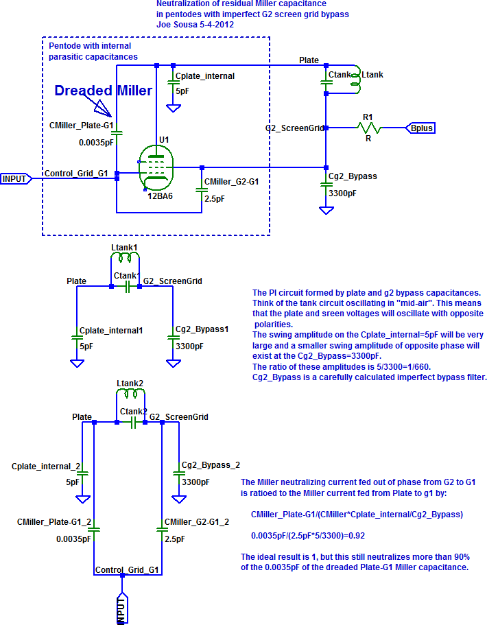
The figure on the right illustrates a common neutralization method for Cgp by selecting the correct value for the G2 bypass cap. Click to enlarge and read the explanation.
Changing the IF2 tube from the 12BA6 with gm=4.4mS and Cg1p=3.5fF to the 19HS6 with gm=9.5mS and Cg1p=6fF required adjustment of the neutralization of this stage to keep the FM frequency response of this stage independent of signal amplitude. When the FM signal gets large, the stage starts to limit, which is very beneficial for FM, but the gm also drops, Which changes the effect that Cg1p and detunes the input tank. In a fully neutralized stage, the gm variation has negligible effect on the input impedance of the input grid.
The effect of neutralization is negligible at 455kHz in the AM IF. The reactance of the G2 bypass cap C19=2.2nF (XC19=160Ω) is also comparable to the 220Ω G2 isolation resistor, which greatly diminishes its effect on neutralization anyway.
This stage was originally neutralized with a reduced G2 bypass capacitor C19=2.2nF (XC19=-j6.8Ω at 10.7MHz). The typical full sized bypass G2 cap is 10nF. A 220Ω resistor isolates XC19=-j6.8Ω at G2 from the shared HV supply. The neutralization is done by the small AC voltage at G2, which couples via Cg1g2 to G1 with the opposite phase of Cg1p=6fF. Cg1g2 is much larger than Cg1p and is not specified, I measured Cg1g2=2.1pF using a square wave attenuator mesurement procedure. The new value for Cg2 was empirically found to be 1nF by selecting the value that made the FM-IF response for this stage independent of signal amplitude.
You may notice that the previous IF1 stage has C18=4.7nF at G2, which is much higher than the 1nF at the IF2 stage. The reason for this is that the total capacitance to ground is explicitly higher, especially with the modified circuit, where it is over 20pF. The current that flows to ground through this capacitance returns to the tank coil via C18, thus creating a larger signal in this stage. The capacitance from plate to ground is a fundamental part of this neutralization scheme to produce a current that returns through the cap bypassing G2.
Correct neutralization was confirmed by verifying that the FM IF response did not change significantly for small vs large signals. The monitoring point for the FM If response was at point "C" in the schematic at the FM limiter stage via a 1Meg resistor. This point gives the amplitude response of the signal, not the FM response as is the case at the discriminator.
List of HiFi modifications
- Overcouple IF1 Transformer with 8pF
- Overcouple IF3 Transformer with 6pF
- Redesign IF2 tank for increased AM BW
- Increase AGC filter cap from 10nF to 57nF to reduced bass distortion from AGC modulation
- Reduce LF bw of loop antenna with 20Ω series resistance
- Reduce first AM envelope filter from 100pF to 39pF to eliminate diagonal distortion
- Reduce second AM envelope filter from100pF to 47pF to eliminate diagonal distortion
- Replace 19T8 AM audio detector with 1N34 to eliminate low level clipping
- Rewire 19T8 AM detector for AVC only. Coupled to 1N34 anode with 39pF (could not delay)
- Replaced IF2 12BA6 with 19HS6 to increase gain. Extra heater drop gained from 6BJ6
- Replaced FM front end RF 12BA6 with 6BJ6 for improved FM and reduced heater drop
- Neutralized 19HS6 by lowering G2 bypass from 2.2nF to 1nF. Reduced depency of FM response on signal strenght.
- Reduced 19T8 triode plate filter cap from 470pF to 60pF for improved audio response at 10kHz.
- Reduced 35C5 power pentode plate filter cap from 10nF to 5nF and rerouted to cathode.
- Added phone jack for external speaker, which disconnects the internal speaker
- Soldered in 1Meg test point at 100k//25pF FM limiter filter before the 12AU6 grid
- Added two 100k resistors in series with ground and the top of the pot for signal metering.
List of repairs
- Replaced silver mica disc caps in IF transformers: AM-IF1, AM-IF2, FM-IF2, AM-IF3, FM-DISC
- Replaced defective 10nF cathode bypass for 19HS6 with 20nF.
- Added 400mA fuse for safety. Normal AC current drain is 260mA. Slow blow is required because the initial current when the tubes are cold the heater resistance is about 6-7 times lower than after warmup. So the initial cold current is about 1.7A.
Click to Enlarge

A few HiFi AM Receivers and Tuners
The minimum criterion is for wideband IF response, preferable with wide/narrow adjustment.
- USA Zenith C845 table radio, 1960, with fixed overcoupled IF
- USA H. H. Scott Stereomaster 330D AM-FM, 1959, high performance with adjustable IF BW
- USA McIntosh MR55 AM-FM Tuner, 1959, high performance with adjustable IF BW
- USA Heathkit PT1 AM-FM tuner 1958 with adjustable IF BW, full wave crystal diode detector
- USA Heathkit AJ-41 AM-FM stereo tuner 1962, adjustable IFBW, doubling crystal diode detector
- Germany SABA Freundenstadt 14 AM-FM stereo table radio, 1964 with adjustable IF BW
- Germany SABA Freiburg Automatic 100-Stereo table radio, 1960 with adjusttable IF BW
- Germany Telefunken D775WK Trop, AM-SW table radio, 1954, coupled Treble and IF BW adjustment
- Germany Philips Capella-Tonmeister 783 Stereo AM-FM-SW, 1959, adjustable IF BW
Going Further
Gain Boost: A further boost in gain is possible by replacing the 12BA6 in IF1 with a 19HR6 remote cutoff pentode, which has twice the gm. The increased heater drop would be recovered by replacing the 12AU6 limiter tube with a 6BH6 without loss in FM performance. The 6BH6 has a sharp cutoff and comparable gm=4.6mS, but with half the heater power of the 12AU6. I tried this mod and verified the increase in AM-IF gain. The FM benefited without any ill effect without any need to re-neutralize this stage.
AM AVC Center Channel Tuning: One way to add a method to tune the AM for the center channel with the external meter, would be to have a separate IF tank sharply tuned to 455kHz driving a separate AGC detection diode. The tank would be driven with a small capacitance <10pF from the primary or secondary of third IF transformer. In this set I am using the 1N34 crystal diode for audio detection and using the detector in the 6T8 for AGC.
The purpose of the AVC "delay" is to keep the AM-IF at full gain until the IF signal reached a certain level at the AVC detector. Now that I am using a 1N34 diode that detects audio with just 100mVp-p, the AVC that is detected by the thermionic diode in the 19T8 does not start detecting until the 1N34 has detected a carrier that produces -0.5V at the top of the pot. The AVC line has -0.96V at this point with the 19HR6 in the first IF stage. This is in effect a form of AVC delay, but just for the smallest signals.
The AVC delay could be increased further to avoid any gain reduction over a wider range of weak signals. One method would be to raise the AVC detector cathode by 1V. A bypassed 1K resistor in series with the 19T8 cathode and a 100k resistor to the 90V supply would raise its cathode by 1V. The AVC detector would not start detecting IF until it exceeded at least 2Vp-p. In order for the FM discriminator diodes and the triode in the 19T8 not to be disturbed, the 150kΩ ground return resistor R23 of the FM discriminator and the 4.7Meg triode grid resistor would have to still return to the common cathode at pin7. The Audio from the ratio detector should also be AC-coupled to the pot to eliminate the 1V offset, but this may not be necessary.
Reduced bass distortion: An option for bass distortion purists would be to install a manual AGC control that would have no self modulation problems at bass frequencies. Manual AGC control is already common in communication receivers. You could tune in the radio under normal AGC and then switch to manual AGC to get the volume back up to normal. I looked at a few AM HiFi tube tuner and receiver designs and they all had real time AGC always engaged. One drawback of having to feed a negative AVC voltage manually is the need to create a quiet negative power supply of about -15V.
Wideband noise clipper: Noise clippers are common in AM communications receivers. They are effective at cutting off narrow noise spikes as might be generated by light dimmers or by the brushes of a motor. The clipping is most effective on a wideband signal. So in this case, you would clip the noise with the full 10kHz audio bandwidth, but then optionally lower the bandwidth for further noise reduction, The same clipping action with narrow band is less effective because the noise spike has been integrated into a wider shape with narrow band filtering, which can't be clipped as much and is also more audible. I did a quick try with an improvised clipping circuit and it worked quite well. The clipper was a 1N34 diode with the cathode at the top of the volume pot and the anode tied to a negative DC level that is twice the detected carrier level, where the modulation peaks normally reach. This was extremely effective, to the point that the spikes were no longer distinguishable from the normal static. The source of the nasty spikes was one of the unfiltered light dimmers in my house.
At some point, I decided to stop "going further', so I could get this article written and published.
Conclusions
The modification of this radio for HiFi AM reception was an excellent vehicle to learn about the design constraints of AM HiFi reception, in particular, and about general AM receivers in general. I was particularly fascinated by the operation of remote cutoff tubes and how to best manage their AVC bias voltages. Discovering unexpected sources of distortion in AM tube receivers was an interesting surprise too. Developing the signal measurement method by forcing equivalent calibrated generator voltages was very useful and I will use it in the future. I imagine that this is how RF/IF signals were measured back then and maybe still today.
Having recently retired from a 42 year career designing analog integrated circuits at Sipex, Linear Technology and Analog Devices, it was great fun to finally have the time to do this project and to be a design engineer 60 years ago!
I dedicate this post to the memory of our esteemed late RM member Prof. Dr. Dietmar Rudolf. He was instrumental in my joining RadioMuseum.org.
Comments and suggestions are invited.
Regards,
-Joe
Joe Sousa, 27.Mar.24