


 Radio-Katalog, Röhren, Halbleiter etc.
5040W/3D (5040 W/3 D)
Land:
Deutschland / Germany
Hersteller:
Grundig (Radio-Vertrieb, RVF, Radiowerke)
Jahr: 1954 – 56
Typ:
Broadcast receiver (Radio).
Im Gegensatz zu Radioempfängern für kommerzielle und/oder militärische Zwecke und den frühen Empfängern für Morsezwecke nennen wir hier Radio bzw. Rundfunkempfänger. Aber: Gemäss internationaler Sprachregelung führt der Radiokatalog Band 1 alle Empfänger mit aktiven Bauteilen als RADIO. Wir unterscheiden hier ebenfalls nicht, ob mit Röhren bestückt, hybrid, mit Transistoren oder/und ICs.Rundfunkempfänger (Radio oder Tuner)
ID = 20139
zurück
Trefferliste
vor
Neue Suche
Techn.Unterlagen: 14 (Für
Mitglieder)
Prinzip
Superhet with a preamplification stage.
Please use «To add informations to model» if you know more! Thanks.
Récepteur TSF superhétérodyne avec préamplification de HF.
Superhet mit HF-Vorstufe.
Super mit HF-Vorstufe; ZF 468/10700 kHz
Anzahl Kreise
11 Kreis(e) AM;
11 FM-Kreis(e)
Wellenbereiche
LW, MW/BC, several SW plus FM (long-, medium-, short waves plus FM). GO (OL), PO (OM), quelques OC et MF (onde ultra-courte, bande FM).
LW, MW, mehrere KW plus UKW.
«mehrere KW» Kann mehrere unterteilte KW Bereiche bedeuten - z.B. 16-25 und 31-49m-Band oder KW durchgehend plus gespreizte Bänder.
Aus den Unterlagen war nicht ersichtlich, ob auch der MW-Bereich unterteilt ist (sehr selten).Langwelle, Mittelwelle, mehrere Kurzwellenbänder plus UKW (FM).
Betriebsart / Volt
AC set plus voltage range.
/ = 2 different voltages
- = voltage from-to
* = «Special»
Apparareil à courant alternatif. Tensions mentionnées.
/ = 2 Spannungswahlen
- = von-bis
* = Fabrikwahl/«Spezial»
Trafo ist nicht immer mit Primär- undSekundärwicklungen versehen. Dadurch kann das Chassis ein gefährlichesPotential führen.Wechselstromspeisung / 110; 125; 160; 220 Volt
Lautsprecher /
Ausgangsleistung
4 built-in loudspeakers of any principle.
4 haut-parleurs.
4 Lautsprecher, meist permanentdynamisch. Mischformen sind möglich - z.B. für Hochtöner. Diese Daten finden Sie eventuell in den Bemerkungen zum Gerät.4 Lautsprecher
/ 8 W
von Radiomuseum.org
Model: 5040W/3D (5040 W/3 D)
Material
Wooden case. Most radios have a wooden cabinet until the WW2. Caisse en bois.
Die meisten Heim-Rundfunkempfänger führen von Beginn an bis etwa Ende 60er Jahre Holz als Gehäuse. Auch frühe Reiseempfänger zeigen Holz (speziell in den 20er Jahren) oder Holz mit Stoffüberzug etc.Gerät mit Holzgehäuse
Form
Tischgerät, Tasten oder Druckknöpfe.
Abmessungen (BHT)
706 x 444 x 318 mm / 27.8 x 17.5 x 12.5 inch
Röhren
9:
ECC85
EF89
Verwendung in NF-Phasenumkehrern, TV-Kippstufen, Multivibratoren, TV-Vertikalablenkung,ECC82
EF89
In Grenzen austauschbar mit EM80 oder EM81, Leuchtbild unterschiedlich, Schaltungsänderung erforderlich.EM85
EBF80
EAA91
Die EF804 ist eine mittelsteile NF-Pentode für Anfangsstufen, speziell für Mikrofonverstärker. Hohe Klingfestigkeit, brumm- und rauscharm. Information aus Funktechnik Nr. 7-1952, Seite 176: Telefunken entwickelte eine Serie Spezialröhren mit langer Lebensdauer und einigen besonderen Eigenschaften für kommerzielle Zwecke, z. B. für die Bundespost und Sendegesellschaften. Es handelt sich um die EF800, EF802, EF804 und EF804S.EF804
18 W- Kraft-Endpentode mit fast doppelter Empfindlichkeit wie die AL5 (oder EL5), vorgesehen für Schaltungen, die für normale Endröhren wie die EL11 entwickelt wurden, aber doppelte Sprechleistung haben sollen.
Ein Zusatz /xxx deuted auf die max. Spannung, für welche diese Röhre selektiert wurde, sonst 250 V.
Die EL12 spez. hat eine Anodenkappe. Die EL6 ist eine Paralleltype mit Topfsockel. [Jacob Roschÿ,13May 2003]EL12
Bemerkung
Grundig Konzertgerät 5040W/3D.
AM/FM-Abstimmung mit Doppelknopf, Motorabstimmung auf 7 Tasten: 1x LW, 2x MW, 2x KW, 2x UKW-Sender.
Im Handbuch des Rundfunk- und Fernseh-Großhandels 1955/56 wird als Funktionsmerkmal irrtümlich automatischer Sendersuchlauf mit Scharfabstimmung angegeben. Es handelt sich um eine elektromechanische Senderspeicherung mit Motorabstimmung der vorgewählten Stationen, im Gegensatz zu den Saba-Modellen mit Motorelektronik gab es bei den Grundig-Modellen mit Abstimmmotor keinen automatischen Sendersuchlauf und keine Scharfabstimmung.
1953/54 Grundig 5040-W/3D Klang (original owner)

 Mehr Bilder
Weitere Informationen zu
5040W/3D (5040 W/3 D) (Grundig (Radio-Vertrieb, RVF, Radiowerke))
Ich habe ein Problem mit dem Suchlauf bei diesem Gerät.2Skalenseile waren gerissen,diese habe ich erneuert.Dieses ist nicht einfach,aber durch die Anleitung welche aufs Gerät hochgeladen wurde gut zu machen.Die Mechanik der Automatic wurde gereinigt.Alles funktioniert jetzt,Nur: Bei drücken einer Taste läuft der Motor kräftig los,er stoppt beim voreingestellten Sender,läuft aber über diesen wohl durch den Schwung hinweg.Der voreigestellte Sender ist nicht zu hören,man muss mit Hand zurückregeln.Ab und zu kommt es vor das der Sender etwas zu hören ist.Die Skalenseile sind ziemlich straff gespanntMir ist klar das dieses Gerät keine Scharfeinstellung wie Saba hat.Ist eine solche Funktion bei diesem Gerät normal,oder kann man das ändern?
Gruss Heinz Hermann Luks
Mehr...
What is the reason that the cathode resistor has no bypass capacitor? I have experimented with my 5040W/3D by adding a 100 Uf 50 volt capacitor and there is a noticable difference in audio gain and bass response, however, I realize that Grundig didn't typically leave anything out. What have I compromised by adding the capacitor, if anything??
Mehr...
This thread is a translation of a German language thread schaltungsanalyse_5040w3d_5_teil , which is 5th in a series of discussions of the circuitry design of the Grundig 5040W/3D. English translations of the previous four threads are here:
Part 1
Part 2
Part 3
Part 4
- Tom A.
(Translation of text originally by Thomas Günzel )
Dear friends of the forum,
First, let me thank everyone who has participated in these circuitry analysis discussions so far. Many people have undoubtedly said "Aha!" a few times when they have understood something for the first time by reading the explanations here.
Before we could proceed with discussions of the AM section, I had to make some significant revisions to our working schematic diagram. The versions I was working with had a lot of errors in some parts.
Therefore, from now on, please use Version 1.4 of the Schematic as the basis for further discussion!
Nonetheless it isn't so simple to recognize all the relationships between different parts of the circuitry. Therefore I have extracted various parts of the circuitry to visually simplify the analysis.
Here is the first question:
The input selection for the short wave bands is presented as follows:
What is the purpose of the combination of C18, BV1443, and C23, which is the same for all short wave bands and therefore must cover the range of 6-18 MHz?
Enjoy,
Thomas G.
Mehr...
Liebe Freunde des Forums
Zunächst mal herzlichen Dank an alle, die bisher an der Schaltungsanalyse teilgenommen haben.
Vielen wird bestimmt durch die kompetenten Beiträge das ein oder andere "Aha" über die Lippen gekommen sein.
Bevor es nun mit dem AM-Teil weitergehen konnte, musste ich eine größere Überarbeitung unseres Arbeits-Schaltplans durchführen.
Die von mir benutzten Vorlagen waren bezüglich der Kontaktbelegung des Schaltaggregats doch teilweise recht fehlerhaft.
Ab sofort also bitte nur die Version 1.4 des Schaltplans als Grundlage für die weitere Arbeit verwenden!
Trotzdem ist es nicht ganz einfach bei den vielen Schaltern sofort alle Zusammenhänge zu erkennen.
Zu diesem Zweck habe ich teilweise einige Schaltstellungen herausgezeichnet um die Analyse etwas übersichtlicher zu gestalten.
Hier nun zur ersten Frage:
Die Eingangsselektion der Kurzwellenbereiche stellt sich wie folgt dar:
Wozu dient die Kombination C18/BV1443/C23 die ja für alle KW-Bereiche die gleiche ist und damit den Bereich 6-18 MHz abdecken muss?
Weiterhin viel Spass
Thomas
Hier geht es zu den bisherigen Beiträgen unserer Schaltungsanalyse:
Teil -1- -2- -3- -4-
Mehr...
(Translation of text originally by Thomas Günzel )
Here are links to Part_1 , Part_2 , and Part_3 and a link to the complete_schematic_diagram.
The FM IF Amplifier (continued)
Dear friends of the forum,
To keep the threads from getting too long, we'll begin Part 4 here.
Here is another excerpt from the schematic diagram:
For an enlarged view, simply click on the diagram below!
Question 3:
On the control grid of the EBF80 there is an R-C circuit (R17/C85) similar to the one discussed previously (R24/C86) on the grid of the EF89 II.
Does this also play a role in gain regulation?
Question 4:
The suppressor grid of the EBF80 is not connected to ground; instead it is connected to the junction of C97, C98, and R41.
What is the purpose of this connection?
Enjoy!
Thomas G.
Mehr...
Hier geht's zum Teil1 , Teil 2 und Teil 3
Der komplette Schaltplan V1.3 hier
Der FM-ZF-Verstärker (Fortsetzung)
Liebe Freunde des Forums
Um die Threads nicht zu lange werden zu lassen, hier nun schon der 4.Teil.
Dazu wieder ein Schaltungsausschnitt:
Zum vergrößern, einfach auf das Bild klicken!
Frage 3:
Am Steuergitter der EBF80 befindet sich eine ähnliche RC-Kombination (R17/C58) wie die schon besprochene Kombination (R24/C86) am Gitter der EF89 II.
Wird hier nochmals nachgeregelt?
Frage 4:
Das Bremsgitter der EBF80 liegt nicht auf Masse, sondern führt zum Verbindungspunkt C96/97_R41.
Wozu dient diese Verbindung?
Weiterhin viel Spaß
Thomas
Mehr...
(Translation of text originally by Thomas Günzel )
Here are links to Part_1 and Part_2.
The complete schematic diagram v1.3 is here.
The FM IF Amplifier
Dear friends of the forum,
Now that we have had a detailed 2-part discussion of the FM tuner, we'll move on to the IF amplifier.
See this diagram for my first question:
Circuitry:
Why was the connection from the FM tuner to the first IF stage made with a twisted pair?
On the primary winding of the first IF transformer there is no capacitor. Does that mean it has only one tuned circuit, and the primary coil is just an inductive coupling?
Production:
Before final assembly, the FM tuner had previously been aligned!
The routing of the twisted pair couldn't be done exactly the same every time. Was it necessary after assembly of the complete set to readjust the coil in the tuner (at the anode of the second section of the ECC85), or was it sufficient to simply adjust the first IF transformer?
I'm looking forward to lively participation. Whoever doesn't have access to post in this forum is welcome to send me (Thomas G. or Tom A.) questions by email.
Thomas G.
[To send an email to me (Tom A.), click on "mail to the author" at the bottom of this thread. To send an email to Thomas G., go the the German_thread and click on "mail to the author" at the bottom of the first post.]
Mehr...
Hier geht's zum Teil1 und Teil 2
Der komplette Schaltplan V1.3 hier
Der FM-ZF-Verstärker
Liebe Freunde des Forums,
Nachdem wir nun den UKW-Tuner in 2 Teilen ausführlich behandelt haben, geht's nun weiter mit dem ZF-Verstärker.
Hierzu nun meine erste Frage:
Warum wurde der Übergang vom UKW-Tuner zur ersten ZF-Stufe anhand einer verdrillten Leitung realisiert?
An der Primärwicklung des ersten Filters ist keine Kapazität. Ist es somit nur ein einkreisiges Filter mit induktiver Einkopplung?
Produktion:
Der UKW-Tuner war schon vorabgeglichen!.
Die Verlegung der verdrillten Leitung konnte aber nie exakt sein.
Mußte im fertigen Gerät nochmals an der Spule (Anode ECC85 II) im UKW-Tuner gedreht werden, oder genügte ein Abgleich am 1. ZF-Filter?
Ich freue mich auf eine rege Anteilnahme.
Wer keine Schreibrechte hat kann mir seine Fragen gerne per Email schicken
Thomas
Schaltung:
Mehr...
I wish to submit an interesting note which I have just observed while performing restoration procedures on the cabinet of my 5040W3D (Majestic) version with motor tuning. . . . . .The final nitrocellulose lacquer coatings will be applied in the next week or so.
I respectfully request some comments which may impact the final procedures during this cabinet restoration.
Replies may be in English or German - it is immaterial to my basic question:
Would there be any adverse effects if I replaced the original decorative "brass-colored" trim (only those pieces on the left and right sides which curve around the side speakers) with the proper solid brass alloy wiring?? The original material is NOT metal on this version. I can not attest to the other versions; nor does it appear that this trim has ever been removed or replaced.
Also, on the Majestic variant, the decorative trim does not connect to either AM or FM antenna systems. And during the refinishing, the stripping chemicals were observed to remove the "brass-colored" enamel or lacquer from what appears to be a hard plastic or vinyl strip (monofilament core). This material is nearly identical to the old "fender welting" strips applied to automobiles when body and fender panels were bolted on (MANY years ago), with the only difference being that this trim material is much smaller in diameter.
I have ordered the category 260 alloy brass wire in sizes 12 gauge (.081"), and 14 gauge (.064"). The actual width of the original trim material groove measures up to nearly .070".
The reason I ask is because I have not seen any forum discussions which relate to this specific topic; and I allude to some earlier comments regarding the interaction of the "wire trim" on some models . . .Reference post 29 to the original thread submitted by Herr Jochen Amend
I have taken many recent photographs of the cabinet and various small trim pieces; and will submit a few to reflect the "before and after" status.
It is my expectation to approach the outstanding quality of work achieved by Herr Martin Renz on his Siemens G7 dual-colored cabinet and others he has displayed. His outstanding in-depth discussion of techniques to apply new lacquer coatings to the various woods on our radio cabinets has also been of great benefit to all members.
The attached photo depicts the temporary insertion of 14 gauge solid copper decorative wire for the purpose of evaluation.
Respectfully,
Robert Sarbell
(Translation of text originally by Thomas Günzel )
Here is a link to Part_1 of this continuing series.
The FM oscillator and mixer
We are now continuing on with the oscillator and mixer stages.
Here are two questions:
1. What is the purpose of the R-C combination R3-C8 along with a choke of about 2 µH?
2. Why is there a resonant circuit (L and C9) between the cathode of the ECC85 and ground?
Part 1 of our circuitry analysis can be found here:
Circuitry_Analysis
I hope you enjoy this ongoing project.
Thomas G.
Mehr...
Hier geht es zum Teil 1
Der UKW-Oszillator und die Mischung
Hier geht's nun weiter mit dem Oszillator und der Mischstufe.
Dazu stelle ich zwei Fragen:
1. Welche Aufgabe hat die RC-Kombination C8-R3 zusammen mit einer Drossel von ca. 2µH?
2. Warum liegt in der Kathodenleitung der ECC85 ein Schwingkreis aus L und C9?
Den Teil 1 unserer Schaltungsanalyse finden Sie hier:
Schaltungsanalyse eines Röhren-Großsupers
Weiterhin viel Spaß an diesem wohl etwas länger dauerndem Projekt
Euer
Thomas
Mehr...
This thread is a translation of a German language thread that will likely be of broad interest to our English-speaking community.
(Translation of text originally by Thomas Günzel)
Dear Radiomuseum friends,
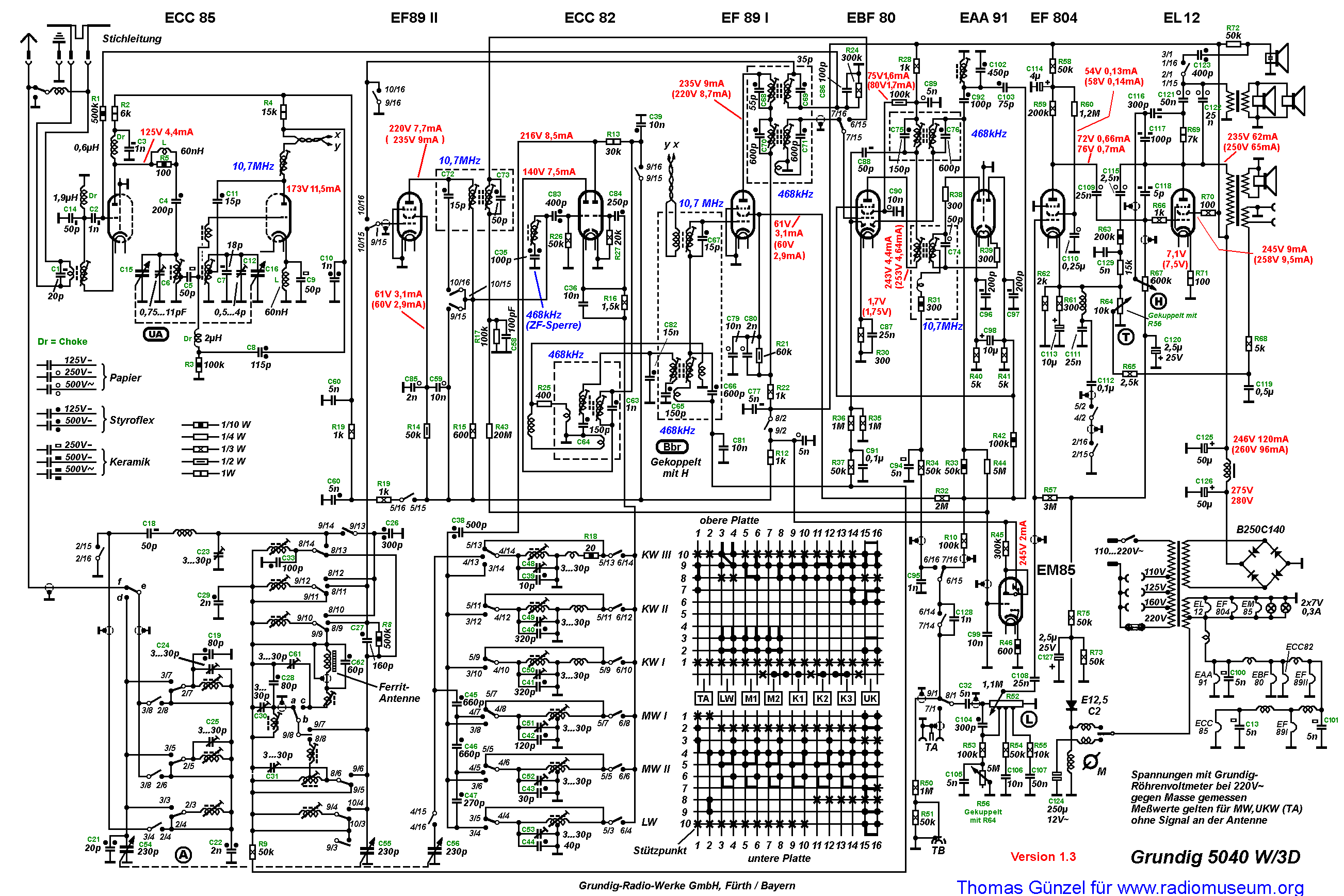
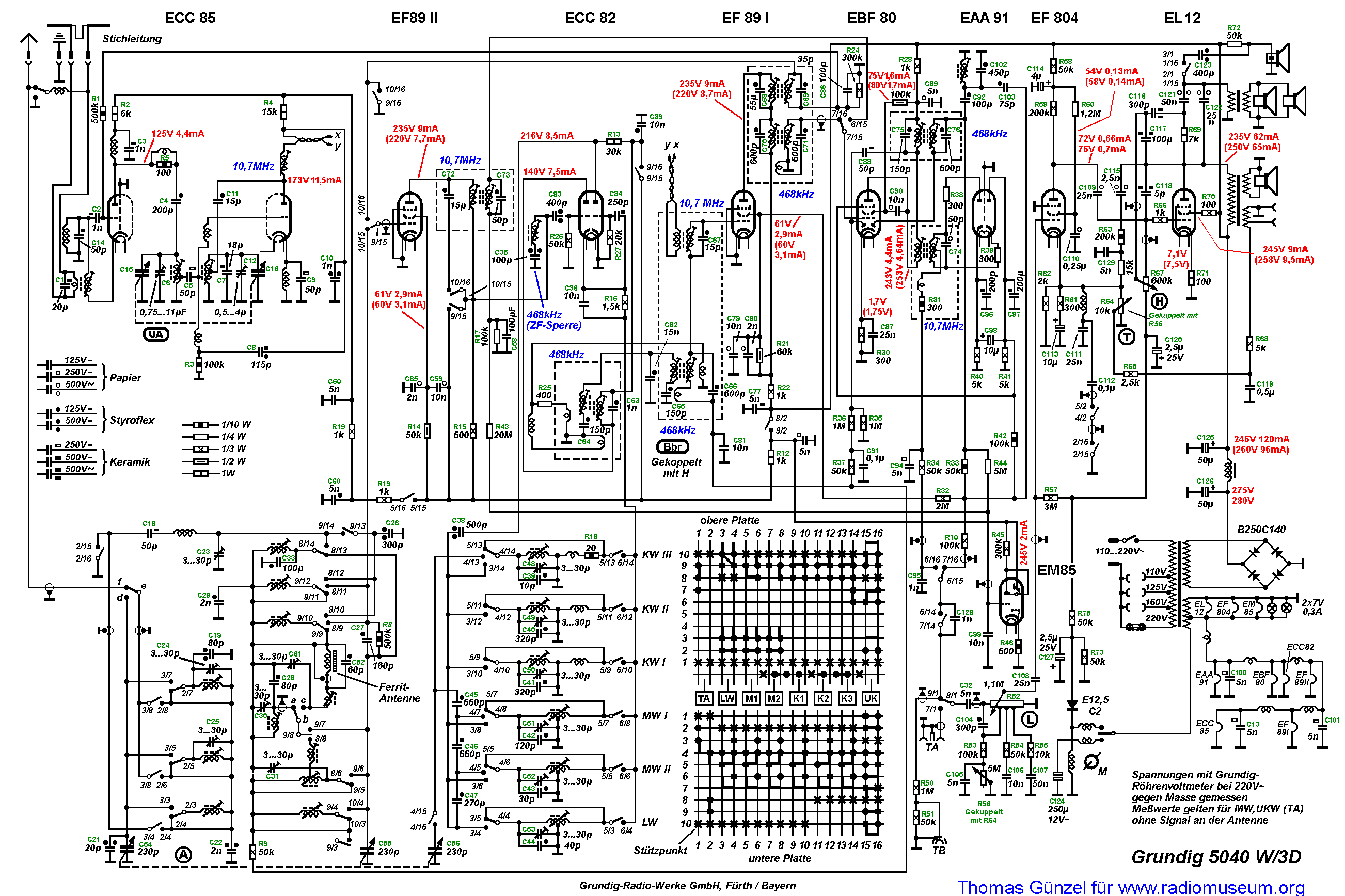
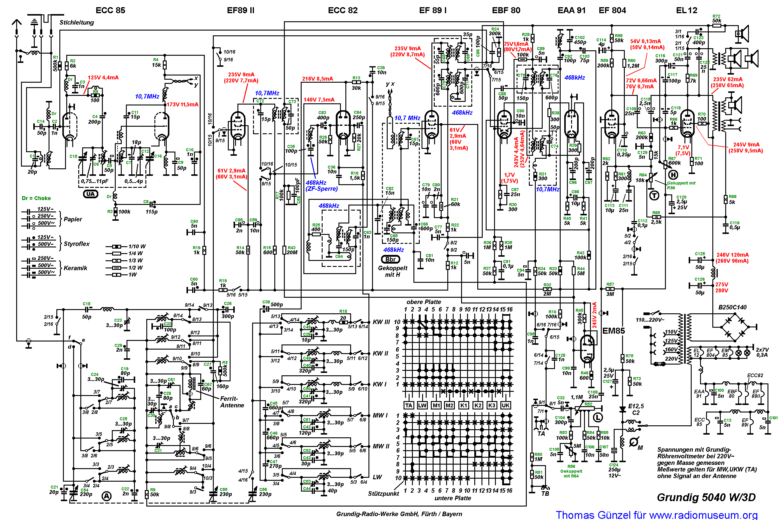
In this thread we will attempt to examine and explain the circuitry of a “Großsuper” from the 1950’s, using the schematic diagram of a Grundig 5040W/3D as an example.
This should not turn into an academic discussion with a jumble of mathematical formulas. Instead, we will seek to explain in an understandable manner the function of various features of the circuitry, from complete circuit blocks down to individual components.
To accomplish this, we have succeeded in persuading none other than Herr Hans Martin Knoll to serve as our tutor. With his specialized knowledge and experience in product development, he is certainly our first choice in this role.
We will also be supported by Mr. Thomas Albrecht, who will take care of providing technically accurate translations of the texts contributed here, so that English-speaking members can participate in this thread.
[Note regarding the translation: If any of you see any problems with the translation, please send me, Thomas Albrecht, an email and I will gladly edit these translations to fix anything that can be improved.]
Translators who can provide parallel translations for other languages would also be welcome.
First of all, we will begin with the FM tuner and work our way through the IF-stage, including the “Magic Eye,” up to the input of the audio stage.
Next, we will handle the AM section and proceed through to the loudspeaker.
To provide for a common focal point for the discussion, I have revised the schematic diagram of the 5040W/3D and provided it in a convenient format (100 kB).
This format makes it easy to cut and paste details from the schematic into discussions as the basis for questions and answers. See the first example in the next post.
The schematic diagram can be downloaded here:
Grunding_5040W/3D_Schematic_Diagram
Mehr...
Liebe Freunde des Radiomuseums,
Mit diesem Thread wollen wir versuchen, die Schaltung eines Großsupers aus den fünfziger Jahren anhand des Grundig 5040W/3D zu erläutern und zu untersuchen.
Es soll keine akademische Analyse mit Formel-Wirrwarr werden, sondern in verständlicher Weise die Funktion des Schaltungszuges, einzelner Schaltungsblöcke und Komponenten erläutert werden.
Zu diesem Zweck ist es mir gelungen, keinen Geringeren als Herrn Hans Martin Knoll als Tutor zu gewinnen, der mit seiner Fach- und Entwicklungskompetenz sicherlich die erste Wahl ist.
Unterstützt werden wir auch von Mr. Thomas Albrecht aus den USA, der für eine kompetente und fachgerechte Übersetzung der Beiträge ins Englische sorgt, damit auch unsere englisch-sprechenden Mitglieder an diesem Thread teilhaben können.
Parallelübersetzer für andere Sprachen sind natürlich auch noch willkommen.
Wir werden zunächst beim UKW-Tuner beginnen und uns über die ZF-Stufe inklusive "Magischem Auge" bis zum Eingang des NF-Teils vorarbeiten.
Anschließend werden wir den AM-Teil bis zum Lautsprecher anpacken.
Damit alle die gleiche Grundlage verwenden, wurde von mir der Schaltplan des 5040W/3D überarbeitet und auf ein handliches Format (100kB) gebracht.
Es lassen sich leicht Schaltungsauschnitte mit Hilfe von Grafikprogrammen ausschneiden um sie als Basis für Fragen und Antworten zu nehmen. Siehe erste Beispiele im nachfolgenden Post
Der Plan kann hier von Jedermann heruntergeladen werden und kostet keine UACS-Punkte:
Schaltplan Grundig 5040W/3D
Damit dieser Thread nicht im Chaos endet, sind zwei einfache Regeln einzuhalten:
1. Fragen stellen darf jeder und sind auch erwünscht.
2. Antworten dürfen nur jene, die sich Ihrer Aussage sicher sind und nicht nur Vermutungen äußern.
Wir wollen hier keine endlosen Diskussionen über "Wenn" und "Aber" oder "Vielleicht"!
Weiterhin sollte beachtet werden, daß Fragen nur zum laufenden Schaltungsblock gestellt werden!
Also keine Fragen zum Klangregler, solange wir noch den UKW-Tuner behandeln.
Als Einstieg und Grundlage möchte ich hier noch auf den hervorragenden Abschnitt "Kleine Schaltungslehre" aus Herrn Erb's Buch "Radios von Gestern" verweisen, der schon sehr viele Einblicke in die Schaltungstechnik von damals bietet.
Ich hoffe auf eine rege Anteilnahme und wünsche Euch viel Spaß und Freude an diesem Vorhaben.
Thomas Günzel
Mehr...
Dear Andreas,
I apologize for answering in English; however, in July 2005 I translated the complete Grundig TI 2/54 document - and I also received a great help from Hans Knoll - to fully understand the
Motor tuning structure, function, and service - even to include "Einstellung der Wanderscheiben-Rutschkupplung" . . . . .
The information is located on page 3, and includes the figures 8 through 11. Figure 8 depicts the technician checking the tension. The instructions state "Bremsmesswert von 320.....350gr.
The complete Grundig T/I document is available in RMorg.
Respectfully,
Robert
NOTE:
Mehr...
Sehr geehrte Sammlerkollegen,
ich habe seit einiger Zeit einen Grundig 5040 W/3D . Leider fehlen bei diesem Gerät die sieben Federn für die Motorabstimmung. Die Federn sind an einem Ende an den Isolierstoffhebeln befestigt. Es wäre sehr nett, wenn jemand mir die genauen Maße der entsprechenden Federn mitteilen könnte. Beste Grüße Andreas Hoppe
Mehr...
Wie jeder weiß, hat der Grundig 5040 3D eine Motorabstimmung!
Bei meinem Gerät fehlt jedoch der Ein/Ausschalter für den Motorbetrieb.
Das heißt man kann das Gerät nur manuell bedienen oder man stellt an dem Seilzug innen am Tastenblock auf ein, dann funktioniert der Motor, aber eine Einstellung per Hand ist dann nicht mehr möglich! Der Motor auf UKW läuft dann aber nur auf 2 voreingestellte Sender, die nicht verändert werden können! Kann so etwas sein?
Danke
Werner Riethmüller
Mehr...
Hallo Forum, aus einer Sammlungsauflösung kaufte ich für 40 Euro dieses schöne Gerät, welches auch optisch noch ordentlich was hermacht.
Mittlerweile habe ich mich ein bißchen mehr mit dem Radio beschäftigt. Nach dem Tausch diverser Kondensatoren spielt es schon ganz gut, ich bin aber mit dem Ausschlag der EM85 noch nicht zufrieden. Bei einem starken UKW-Sender erreiche ich nach dem 5M (den habe ich geprüft, wie auch den an der Anode) am Gitter eine Spannung von knapp -2 Volt, davor sind es ungefähr -3 Volt. Das führt etwa zu einem halben Ausschlag der Röhre. Beim gleichen Sender habe ich an den beiden Seiten des Elkos an der EAA91 ca. +12,5 Volt bzw. -12,5 Volt. Durch ganz minimales Nachgleichen der beiden ZF-Filter habe ich hier in der Summe etwa 5 Volt rauskitzeln können. Sind diese beiden Werte in Ordnung, ich hätte da etwa doppelt soviel erwartet ? Auf AM ergibt sich das gleiche Bild: die EM schlägt nur ein Drittel aus, hier ist meiner Meinung nach auch zuwenig "Druck auf der Leitung". Wie hoch ist denn die Spannung, die zu einem Vollausschlag der EM85 führt ?
Es wäre nett, wenn jemand den Originalplan hätte, der Wiesmüller-Plan ist nicht so schön lesbar.
Gruß & Dank voraus
Holger Pflug
Mehr...
Dear Colleagues,
After some research into the UKW (FM) bandwidth, I am perplexed as to how difficult it might be to slightly "increase" the 100Mhz (or 104 Mhz) within the European radios to avoid the use of an add-on FM converter or FM expander.
While stationed in Japan from August 1965 until August 1968, in order to receive the Japanese FM stations on US made radios, there were small FM converters sold which covered the 76 - 90 Mhz range, and had circuitry to produce the IF 89Mhz (+/-500khz). The unit was powered by 6 UM-2 (1.5v D-size batteries) and used three transistors. Power consumption was 1VA.
I realize the above explanation relates to a decrease in the FM bandwidth - my question relates to a slight increase.
Would the additional modifications to the present circuits be sufficiently difficult to increase the FM reception range by 1 or 2 Mh??
Respectfully,
Robert
Mehr...
Literaturhinweis: Unter http://www.radiomuseum.org/forum/additive_mischschaltungen_in_den_am_wellenbereichen.html finden Sie ausführliche Informationen zum Thema Additive Mischung in den AM-Bereichen.
Unter: http://www.radiomuseum.org/dsp_forum_post.cfm?thread_id=25496
habe ich eine erweiterte Version , mit grosser Auflösung,eingestellt.
Hans M. Knoll
Herr Knoll, I have recently bought the model 5040W3D from ebaY seller in the US. I have copied the 4 sheets of Technical Information you referred to in your forum post. Do you, or any other radiomuseum member know if the information was translated into English. I believe I have seen a reference for an export model as Grundig 5040W/3D "Ausfuhrung B" . . . I am beginning the complete restoration of this impressive model, and would be most appreciative of any technical hints. I have performed some service (in 1976-1978) on the "signal sensing tuners" employed in the US automobile radios of the mid-1950s. . . .with the "Wonder Bar" tuning. Is the Grundig system quite similar with an unlatching and locking (stop) mode dependent upon signal strength? Thank you so much Respectfully, Robert I only changed the language flag (Ernest). You can delete my text by editing and your name will be there as editor.
Mehr...
Beschreibung der Motor- Abstimmung der Grundig-Serie 1954, mit 4040W/3D, 5040W/3D, 5050W/3D
