History of the EQ40/EQ80 enneode Frequency Detector - pt2
History of the EQ40/EQ80 enneode Frequency Detector - pt2

Introduction
In part 1 I have presented the EQ40/EQ80 enneode valve development and its basic characteristics. In this part I will present the applications of the EQ80 as FM and coincidence detector.
The EQ40 and EQ80 used in Television receivers
At this stage, it is interesting to explore how the EQ80 FM detector application circuit developed over time. The first topology is the one used in the home-built TV receiver of my father, based on the latest reference design as used inside the Eindhoven Philips Radiobuizen Lab I (the Radio Valve Laboratory, RBL) mid-1948. The circuit diagram of the sound bar is shown below.
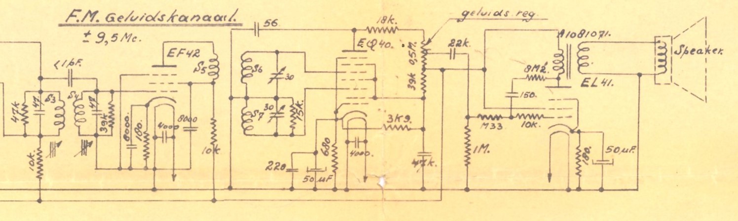
[ FM audio channel of the 1948 Home Built Television Receiver of Piet Hooijmans.]
Interestingly (or maybe not) the circuit used in the August 1948 home built TV, in line with the latest reference design, is almost identical to the circuit concept of Fig10. Specifically, R1-R4 are all exactly the same value in both implementations. The main differences in my father's TV are (1) a damping resistor of 15k in the g3 tuned circuit (2) an additional anode capacitor to ground of 56pF, likely to give stronger LPF action at the output and (c) insertion of the volume control potentiometer in the anode output.
The next instantiation is the Philips TX400U-01, the first commercially produced Philips television set, launched in 1950, and the first set in the world supporting the new 625 lines "Gerber" CCIR-B system. (The TX500 was launched one year later, featuring a larger picture tube but otherwise identical). The TX400 could receive four channels in the VHF I band (41,25 to 62,25MHz) and used a picture-carrier IF of 23,5MHz. With a picture-to-sound carrier distance of 5,5MHz of the CCIR-B standard, the resulting sound IF was 18,0MHz. Although the component values are not readable from this circuit diagram, conceptually it is still the same basic circuit as in Piet Hooijmans' TV and the published reference designs, but in some ways even further simplified, almost certainly to facilitate manufacturing. All in all one can conclude that the basic application of the EQ80 as television FM detector was stable since 1948, and the basis for all Philips television sets from 1948 till at least 1952.
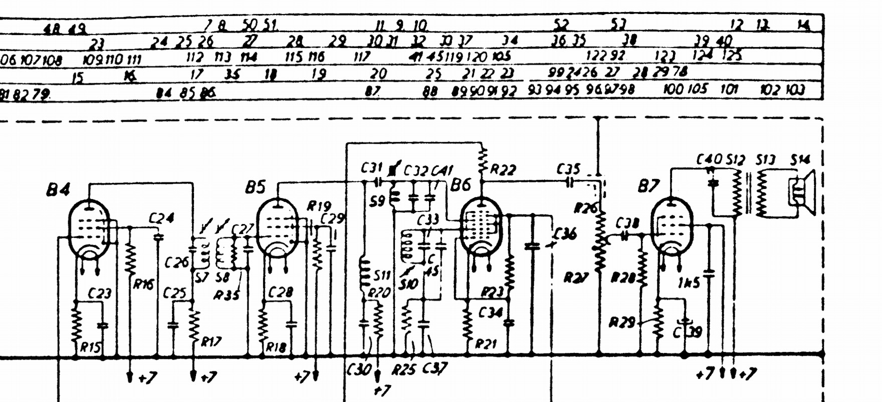
[ The sound branch of the TX400U/01, the first commercial 625-line Philips Television receiver. B4 and B5 are EF80 intermediate frequency amplifiers, B6 is the EQ80 FM detector and B7 is the EL42 audio power amplifier.]
After the first-generation television receivers TX400/500 the EQ80 was used in one more generation of Philips sets: the TX701 projection TV and the TX1410. The TX700 series used in-cabinet rear projection on a much larger viewing screen. This was undoubtedly an effort to provide larger screens while the technology for direct viewing picture tubes was still in its infancy. A high intensity MW6-2 projection tube illuminated via three mirrors and one lens a 45x34cm screen. Which was at the time (1951) a wide screen! The TV reception chassis inside the TX701 was fully identical to that of the TX400/500, with 23 valves including the EQ80. There was a second chassis with 9 valves providing the 25kV supply voltage for the MW6-2. The TX701 price at introduction was 1390Hfl, quite an amount those days.
In 1952 the TX1410 and TX1710 were introduced, which were upgraded models. The TX1410/U, the Dutch-produced model but also manufactured in Italy (Monza), was based on the German model TD1410. It had a slightly larger picture tube than the TX400/500, but especially upgraded sound: a balanced audio output stage using two ECL80's plus tone control. For a nice description of this TV set see the Technisch Museum site. The 1410-series (both TX and TD) also introduced the 10-channel (VHF I and VHF III) tuners. An interesting feature, especially used in Germany, was that the set could also receive radio FM transmissions. In that mode the supply to all picture related sections could be switched off. The TD2312 and TD2314 were a next generation rear projection TV, but based on the TD1410 chassis with all features mentioned. The TX1701 was an upgrade of the TX700, while the TX1714 used the new platform.

[The sound chain of the Philips TD1410U, the last platform to use the EQ80 FM detector. Here we see it used in combination with a dual ECL80 balanced audio end stage. [Philips TD1410 Service Manual]]
Next to Philips there were a n umber of other manufacturers of TV sets using the EQ80. Most of them were in Germany (Saba, Siemens, Graetz), Switzerland (Albis, a JV between Telefunken and Siemens, Tonfunk) and Italy (Irradio, Magnadyne, Minerva). But interestingly there was also van der Heem, in Den Haag, the Netherlands, bringing out its KY311U under the brand name Erres. (Van der Heem/Erres was for many years an independent competitor of Philips, only to be taken over in 1967, after which date Erres continued to be used as a sub-brand). These were all released in 1952-1955, after that date no more television EQ80 usage is known.
The EQ80 in radio receivers
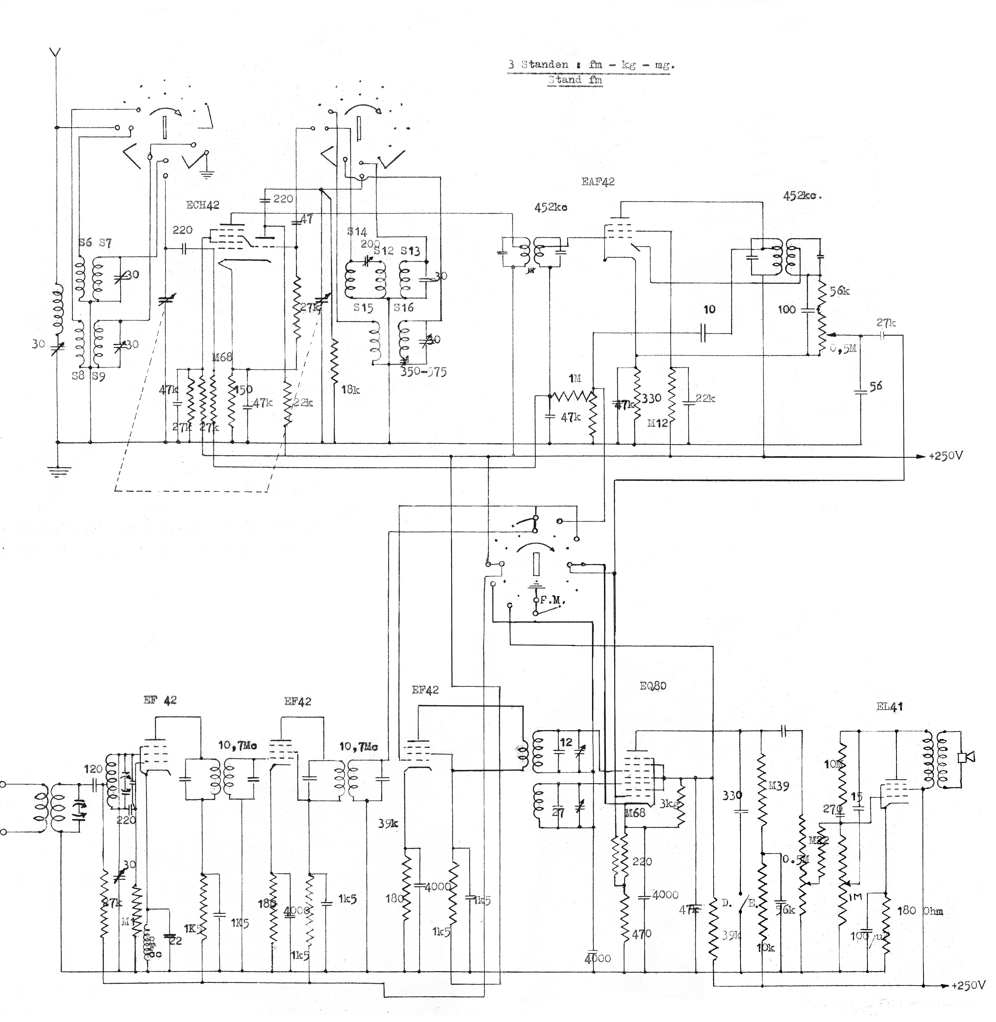
Obviously the EQ80 was also intended as detector tube in FM radio receivers. Here too we can make use of the development report of Bert Dammers and Piet Hooijmans, already quoted earlier in the section of the EQ40 optimization. The reference schematic of an FM receiver was - apart from the RF section with an EF42 and ECH42 mixer-oscillator - very much like that of a television sound chain as described above: an EF42 and EAF42 as IF amplifier, followed by an EQ40 demodulator and EL41 power amplifier. (The additional diode in the EAF42 was not used in FM mode, making it effectively two EF42's as in the TV IF). Below is the circuit diagram of the FM receiver as per Piet Hooijmans' report.
.jpg)
[ Reference design of the EQ40-based Philips FM receiver, 1948. This was the starting point for the investigations into a combined AM-FM receiver. ]
The problem was, however, that in the market there was hardly or no need for FM-only receivers; given the legacy AM transmission any commercial product needed to be combined AM-FM reception. This was exactly the ambition of the project by Dammers and Hooijmans, which they explain as follows:
Introduction
The intention was, starting from an FM receiver using the following tubes
EF42 - ECH42 - EF42 - EAF42 - EQ40 - EL41 - EZ40
RF mixer 1st IF 2nd IF detector power amp
to make this receiver also fit for AM reception.
The circuit diagram of the original FM receiver is shown in Fig. 7.
In this report we will discuss the IF section, the detector and the LF part of the combined AM/FM receiver. The difficulties in combining AM and FM in the RF and mixer circuits are not yet fully resolved. Plans for further improvements will be indicated.
During AM reception the tubes have the following function:
EF42 cathode – grid 1 works as AGC diode
EAF42 IF and detector
EQ40 LF amplifier
EL41 power amplifier
 Essentially what they tried to achieve was implementing the combined AM-FM reception without adding valves (to reduce the cost). To this end the AM detection was not done in the EQ40, but used the single diode in the EAF42. Because of the low conversion gain in this peak detection the EQ40 was used as an analogue amplifier. Which was of course an expensive solution, since more than half of the grids in the valve was effectively not used. This is also visible in Fig.21: g3 and g5 (the control grids in case of FM detection) are connected to g2-g4-g6, giving one enormous screen grid g2-g3-g4-g5-g6-g7, reducing the valve to a single albeit expensive tetrode. This was nevertheless seen as a useful application, because it also appeared in the EAB and Philips Review articles.

[ This is almost certainly the AM/FM-receiver prototype as developed in the Philips Radiobuizen Lab in 1948. In the lower centre is the ECH42 RF valve, then to the right two EF42's and in the back first the EQ40 and then the largest EL41. Power supply was external. ]
From the report of Dammers and Hooijmans it becomes clear that trying to make an AM-FM receiver with the limited number of valves proposed was a real nightmare. Although the AM IF (452kHz) and FM IF (10.7MHz) were far apart in the frequency domain such that the resonant circuits for filters could be stacked, there were many cumbersome switching issues. E.g. around the EQ80, where inputs needed to switch from g3 and g5 for FM to g1 for AM. At the end of the report they suggest to fundamentally change the functions of the tubes, depending on the mode. So, in AM the ECH42 would be used as mixer-oscillator, but for FM reception they proposed to use the first EF42 as self-oscillating mixer. They conclude (March 1949) this concept to be very interesting, with lots of potential, but recommend further investigations.
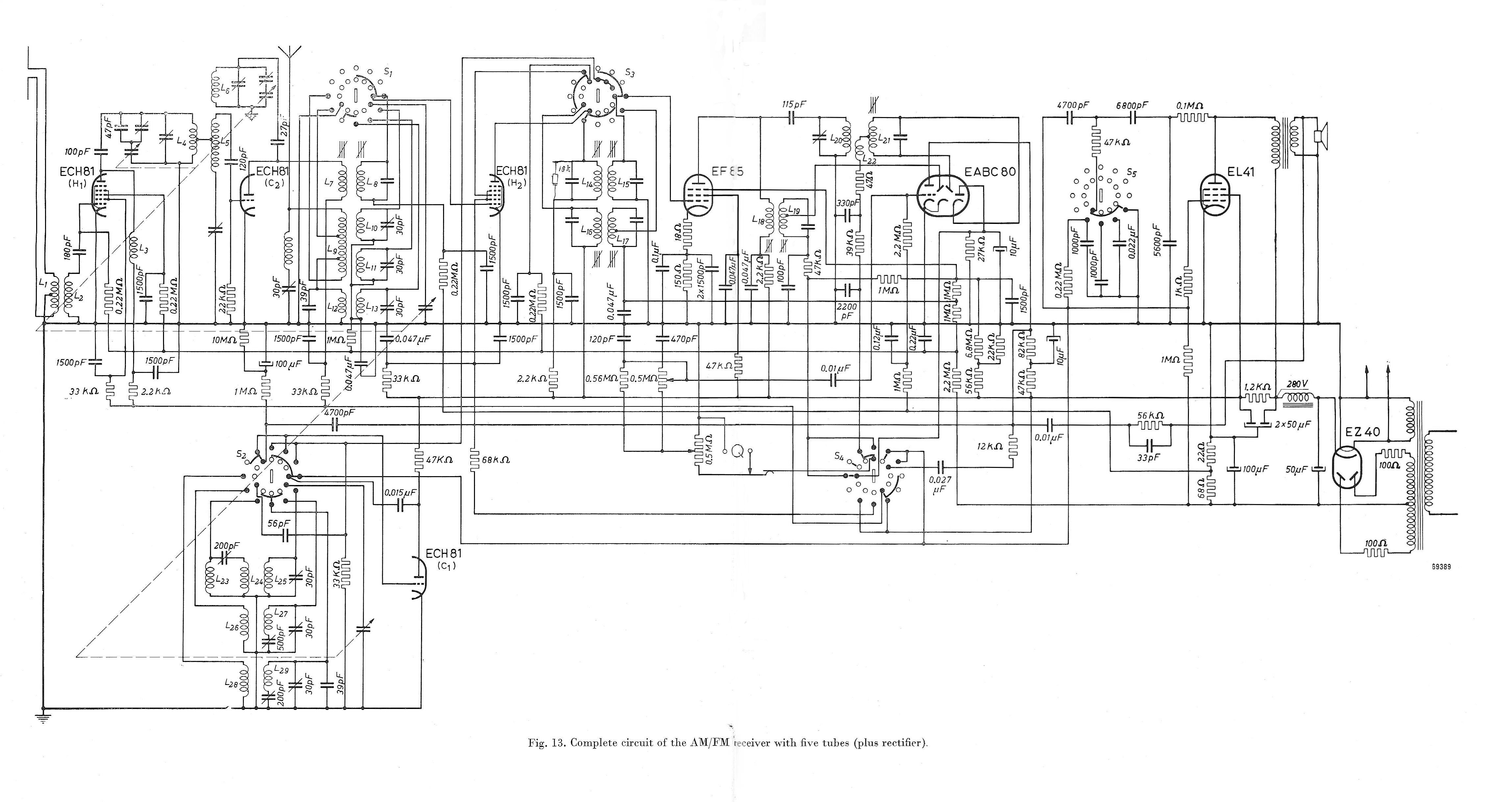
Investigations have almost certainly continued in this direction, but after dropping the original boundary condition that no extra valves were allowed. Efforts to combine the AM and FM RF and IF sections were given up, and each branch was allowed its own line-up. For AM this were the ECH42 and EAF42, whereas the FM used three EF42's. The EQ40 as FM detector or audio amplifier and the EL41 power amplifier end valves were shared. This information is based on a circuit diagram I found in, but not officially part of, the report by Dammers and Hooijmans, so I assume this was an update from later investigations that my father added to his file. The circuit diagram is shown below. I dare to suggest this was likely the ultimate radio receiver design using the EQ40/EQ80.
The use of the EQ80 in (FM) radios seems to have been rather limited. This is partly because actual FM radio transmission started late in countries like The Netherlands (1954) by which time the EQ80 had been replaced by cheaper solutions (see next). Italy is a country were FM was apparently introduced as one of the first, since from 1951 especially Megadyne Radio (Torino) introduces a series of AM/FM radios FM3 to FM9, later followed by FM304-309. The actual design was not based on a known Philips reference design and used a mix of legacy and modern valves instead. But in all models the FM detector used the EQ80 according the Philips reference application design.
Another, and in fact almost the only, major user was the German company Saba (Schwarzwälder Apparate-Bau-Anstalt in Triberg), which brought out a series of luxury AM/FM radio sets called Freiburg, Meersburg and Villingen in 1951-52. These were original AM-only chassis with an additional so-called "UKW-S Einsatz" module taking care of the full FM sound reception. Physically it was a metal box with four valves, an ECH42, two EF42's and the EQ80. This looks suspiciously like the last Philips FM reference design of the FM chain, so I assume this was based on the Philips/Valvo solution. In 1952/53 Saba came with a last chassis containing the EQ80, the Konstanz. On this one the FM chain was identical but integrated on the main chassis.
A last one worth mentioning is the Siemens SH705W "Gross-Super", a high-end AM/FM radio set. Interestingly this seems to be based almost 1:1 on the above Philips reference design for shared AM/FM valve use. It used the ECH42 and EF42 for the RF/IF, an EAF42 IF amplifier, EQ80 FM-detector, EM4 tuning indicator and EL41 end stage. So far it looks that this was the only Siemens set using this architecture apart from an Italian-built Siemens set coded S841. In this one the FM detection using the EQ80 and AM-detection using the EBL41 were split.
The only application I found of EQ80 use in radio FM detection by Philips was again a high-end platform: the FX700 and FX800 radio-record player combi's. The FX723A was the first, followed by the FX824, which was also produced in the US under the Norelco brand. The ultimate model was the FX804 (also built in Italy as FI804), which was a combined AM/FM radio, record player and tape recorder. The FI850, again a dual mode radio-record player introduced in 1955, might well have been the last commercially launched consumer set using the EQ80. This supports the assumption that for radio the EQ80 was only affordable in the high-end segment, where cost pressure was lower.
The fact that the EQ80 was only used in the new and expensive television and FM-radio applications, for not more than four years (roughly 1951-1954), and in a period that most European economies were struggling out of the post-war recession, makes that the number of EQ80's actually used in these sets must have been limited. My guess is some tens of thousands in total.
The EQ80 replaced

 The mere fact that Piet Hooijmans was working hard on the applications of the EQ80 was unfortunately not enough to guarantee its broad use. In retrospect one can probably say that within the scope of valves it was one integration step too far. The same still happens today in IC integration, where there is for each function (or set of functions) an economic limit for profitable functional integration. Sometimes it is technically possible to integrate more, but the integral cost will be higher and/or customers are not willing to pay the associated price. It looks the same happened with the EQ80. The FM-detection function can also be performed with cheaper valves, and for dual mode AM/FM receivers the EQ80 made things unacceptably complex. Unfortunately, especially radios had to be dual mode and provided the highest volumes, so this was a major blocker for using the EQ80.
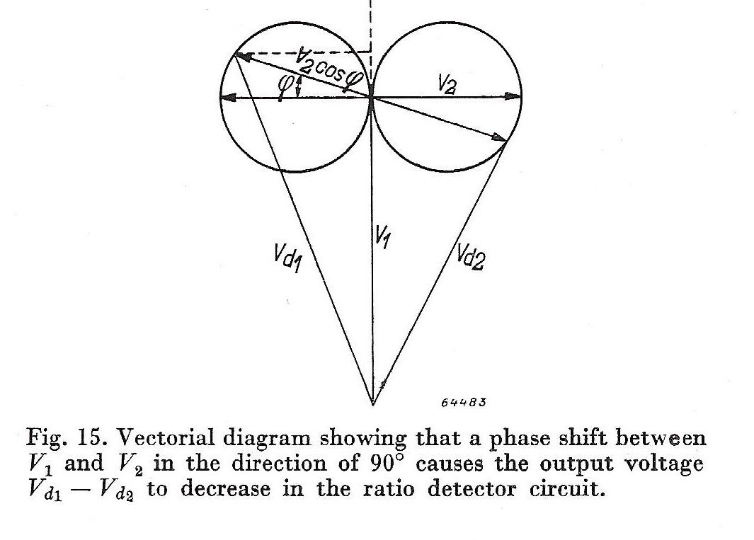
Consequently work started quickly on integrally cheaper detection architectures. The comparison table in the section "The EQ40 phi-detector" above shows that after the EQ40, the ratio detector comes out second best. The Ratio Detector concept is shown in Fig.14. Essentially it is a modified Foster-Seeley, where the two diodes also perform the amplitude limiting action. The voltage at the top of the secondary coil Ls is detected by diode 1, which as a voltage between anode and cathode Vd1, and the output current flows through R1. Similarly, the bottom voltage of Ls is detected by diode 2, with voltage Vd2, and flows through R2. Because from DC perspective the two diodes are in series, and the current through both will thus always settle to be identical. At point A, the LF output, the difference voltage (Vd1/Vd2)/2 is thus measured, which shows (along the circle) an amplitude relative to the input instantaneous phase (or frequency) deviation from the centre frequency.
Sound detection
For this application the special F.M. detector and limiter valve, Type EQ80, is available. In other detector systems, operating with a double diode, the EB91 may be used.
This already suggest the introduction of and conversion to the ratio detector, as happened in radio. However, in contrast to the AM-FM radio were the EABC80/UABC80 combined AM and FM detector was used for many years, television quickly made the move to semiconductor diodes. Ratio detectors with two OA81 germanium diodes were introduced in 1954, thus eliminating valve-based FM detection.

A very last EQ80 design
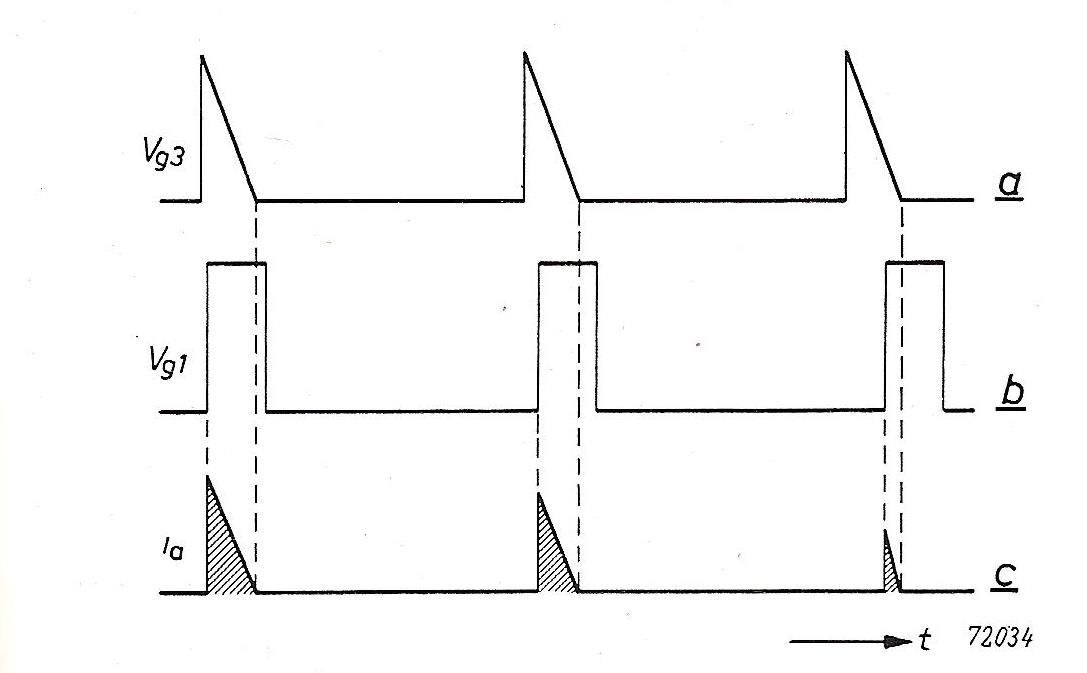 While the EQ80 was steadily pushed out of its FM detector role, all of a sudden a new application popped-up. Descriptions can be found in EAB 1953 No.3 pp.72-80 "Application of the ECL80 and EQ80 tubes for flywheel synchronization circuits" and in the mentioned Philips Electronic Valves part IIIC pp.171-176. As the title mentions, the EQ80 is used to synchronize the multi-vibrator for the vertical deflection with the synchronization pulses and the line frequency of the received video signal. In this application not two, as in the FM detector, but three control voltages are applied to the valve. The clipped video signal is applied to g1 in such a way that only the synchronization pulses will drive g1 to a negative voltage, allowing anode current. The oscillator output is applied to g3, while the flyback pulses are applied to g5. Now only when g1 and g3 and g5 are positive an anode current flows, where the amplitude is dependent upon the amount of overlap of the pulses. With a negative feedback loop the anode current can thus be used to control the multi-vibrator frequency to be identical to the line frequency of the received signal.
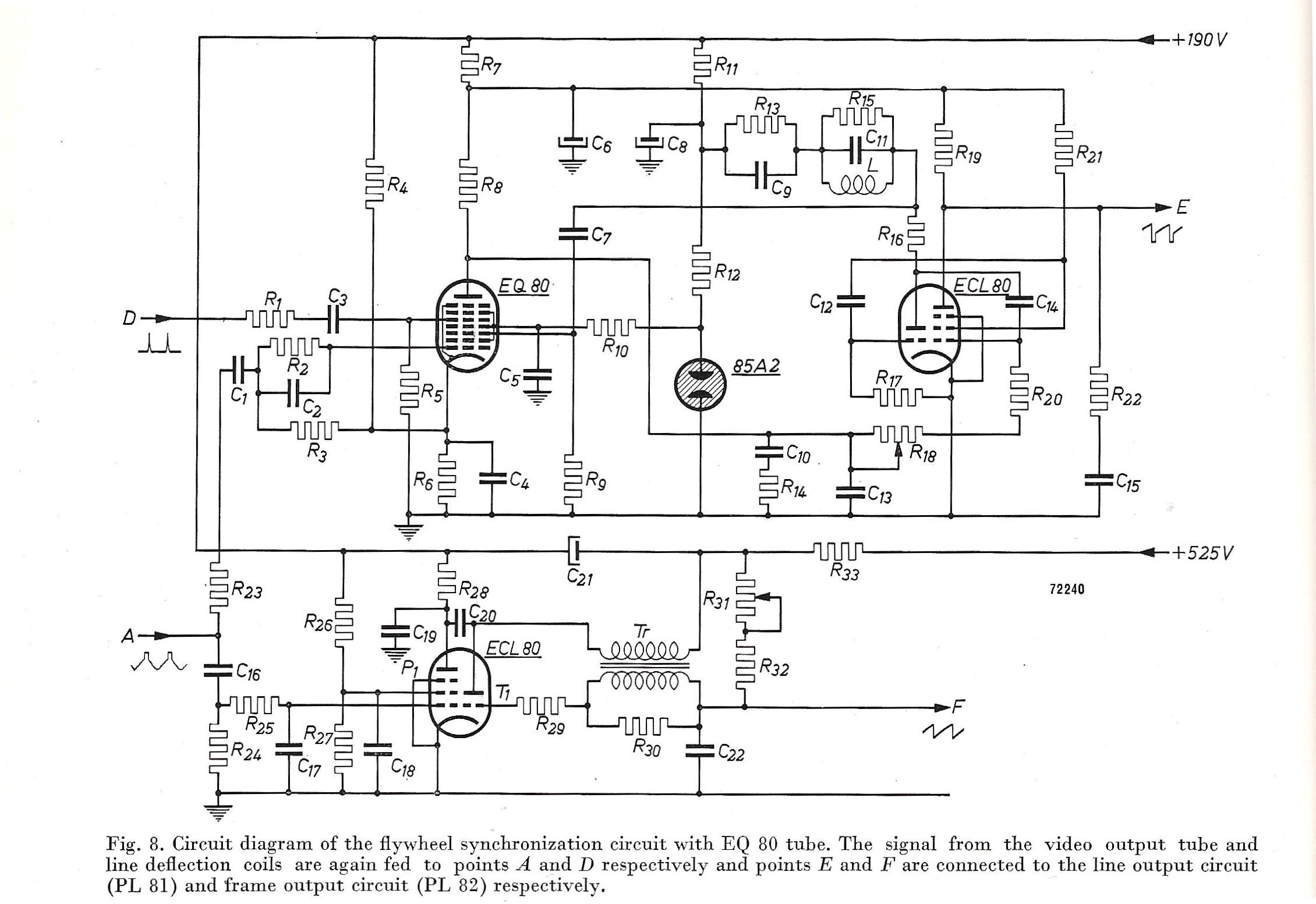 Although this application also clearly shows the capabilities of the EQ80 as coincidence phase detector, the problem probably remained as it was for FM detection: technically a perfect solution, but too expensive, and also achievable with cheaper valves.
I haven't found a single TV set using this concept, and I assume that it was never implemented in an actual television receiver. As such it can be considered as the last effort to push the application of this valve, although without a positive result. It marks the end of the EQ80 in commercial receiver applications.
Still, the world is full of surprises! Because when I obtained a copy of Volume IIIC "Data and Circuits of Television Receiver Valves" of the Philips Electronic Valves series by the RBL engineer J. Jager it not only covers the EQ80 application extensively, including the coincidence detector above. But at the end of the volume is a reference 625 line television receiver that contains two EQ80's; one as FM detector and one as coincidence detector for the line time base oscillator! In line with the method used in my story on the history of television development by Philips, I will call this design RBL6. It was linked to the TX1410 platform and especially TD1420 set from 1952. It clearly shows how much the Radiobuizen Lab continued to push their pet EQ80, up to the last moment when the valve was replaced by the PABC80 (for FM) and the OA81 (as coincidence detector).

Other use of the EQ80

 Apart from the consumer applications described above in detail, the EQ80 has undoubtedly also be used in professional applications. The problem is that these are much more difficult to find, so I will have to limit myself here to the single one described in the Philips Electronic Application Bulletin of January 1952 "Automatic tuning control of HF generators with variable load". The application is a 13,56 and 40,68MHz diathermy (RF heating) medical device with a capacitive dipole-like antenna. Because unknown loads (human bodily parts) will be positioned between the antenna poles the transmitter/generator will de-tune, severely reducing the heat transfer efficiency. The article describes a feedback and control loop using two EQ80 phase detectors in a balanced arrangement.
In Fig.5 we recognize the EQ80 phi-detector circuit, but now in a balanced arrangement. On both g3 grids the reference voltage Vref coming from the RF generator is applied. On both g5 grids the two HF voltages coming from the antenna pick-up coil are applied. The two voltages are needed because the control needs to work in both directions (positive or negative), depending upon capacitive or inductive antenna de-tuning.
Fig.6 shows the principal voltages and the analogue AND-operation that the EQ80's perform. In case Vhf1 and Vhf2 are exactly in quadrature the two EQ80 output voltages have the same average (low pass filtered) DC-value. Deviations from 90degrees will make the one output higher and the other one lower.
The full control circuit, using two PL21 gas-filled thyratrons, is shown below.

EQ40/EQ80 closing remarks
Forty years ago, when carefully looking inside my fathers old home-built TV receiver, I was always intrigued by the EQ40, especially when my father told me this was the only nine-electrode enneode valve ever developed. It therefore gives me enormous pleasure to have written this - very personal - history on the EQ80, which turned out to be so much more interesting than I had anticipated. I had never realized that the EQ80 was so intimately linked to the first television and FM radio receivers, and that it is thus part of a very exciting period in the development of consumer electronic devices we take for granted today. This was made all the more interesting - at least to me - by the fact that my father in his younger days was part of these developments, it gives me an enormous sense of pride. Since my father never threw away anything of interest, I'm happy to possess the reports from his days at Philips Radiobuizenlab as well as the EAB journals, which were an invaluable source of information when writing this story.
As with every historical investigations the writer is forced to some level of interpretation; one doesn't have access to all data, and the story is therefore never complete nor perfect. The same will be true for my EQ40/EQ80 history. I look forward to any feedback or coments.
© Pieter Hooijmans - original at maximus-randd com/EQ40-and-EQ80
To thank the Author because you find the post helpful or well done.