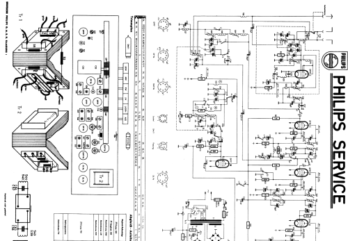
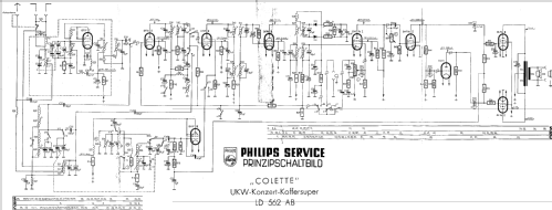
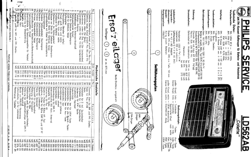
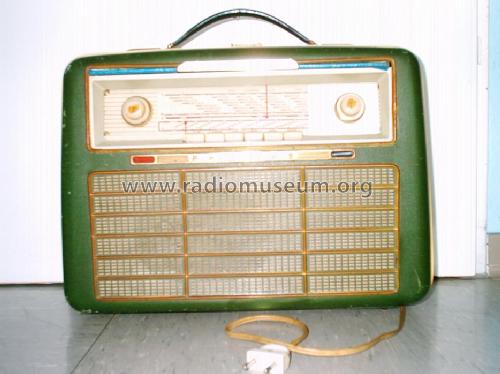
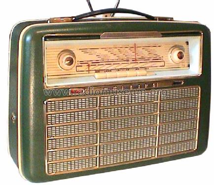
Colette LD562AB
Philips Radios - Deutschland
- Paese
- Germania
- Produttore / Marca
- Philips Radios - Deutschland
- Anno
- 1956–1958
- Categoria
- Radio (o sintonizzatore del dopoguerra WW2)
- Radiomuseum.org ID
- 7036
-
- Brand: Deutsche Philips-Ges.


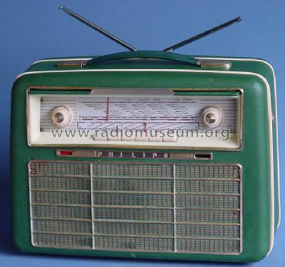
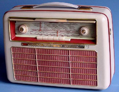
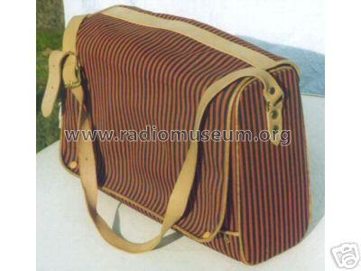
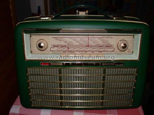
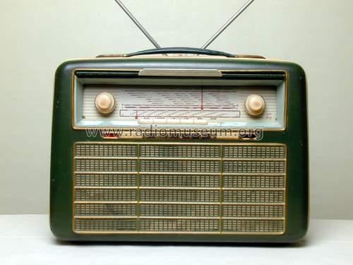
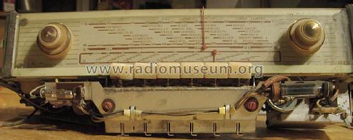
Philips Colette LD562AB


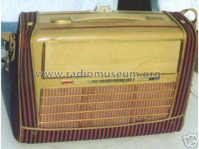
Quelle: eBay Deutschland
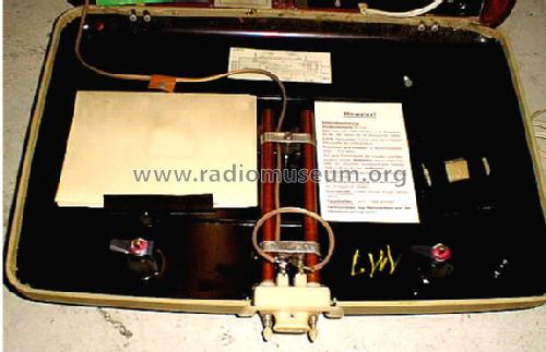
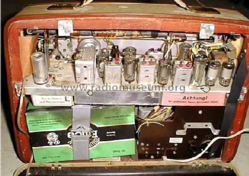

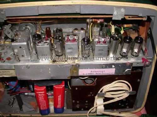

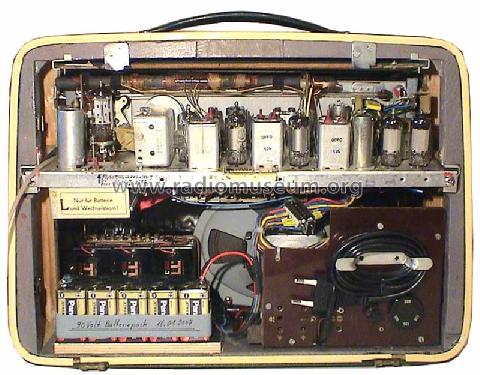
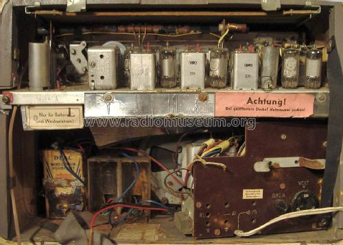
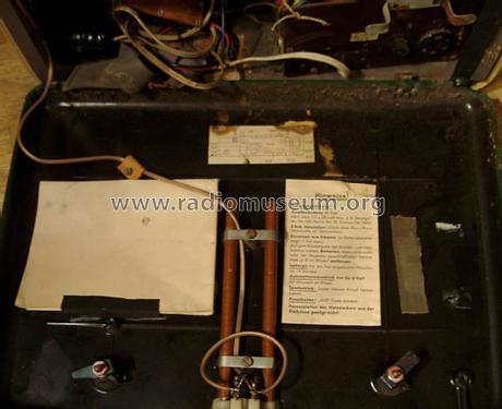
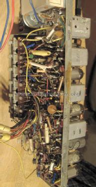
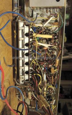
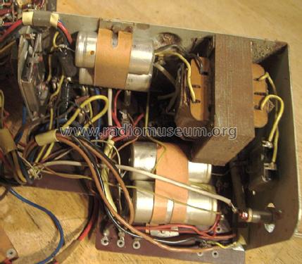
Philips Colette LD562AB, innen
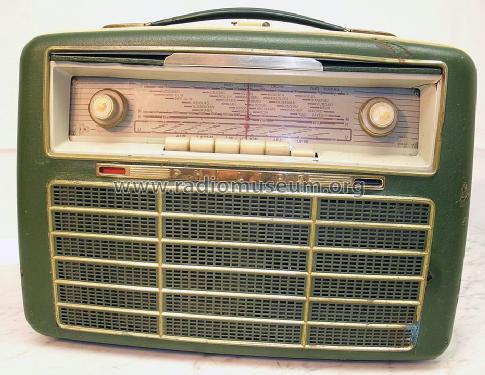
Überarbeitetes Bild LD562AB Außenansicht
Überarbeitetes Bild LD562AB Innen

d_philips_ld562ab_front.jpg
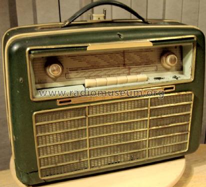
Case a bit damaged but otherwise complete.
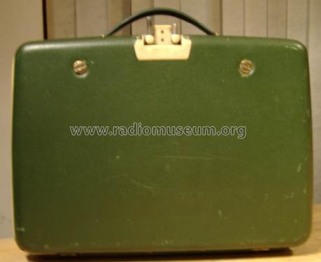
Case a bit damaged but otherwise complete.
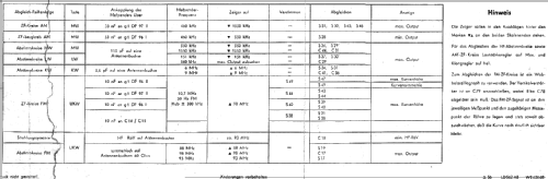
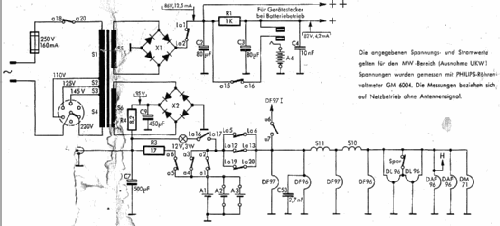
Clicca sulla miniatura dello schema per richiederlo come documento gratuito.
- Numero di tubi
- 10
- Principio generale
- Supereterodina (in generale); ZF/IF 460/10700 kHz
- N. di circuiti accordati
- 6 Circuiti Mod. Amp. (AM) 10 Circuiti Mod. Freq. (FM)
- Gamme d'onda
- Onde medie (OM), lunghe (OL), corte (OC) e MF (FM).
- Tensioni di funzionamento
- Rete / Batterie (ogni tipo) / 110-220 / DEAC D5,5 & 1,5 & 90 Volt
- Altoparlante
- AP magnetodinamico ellittico (magnete permanente e bobina mobile).
- Materiali
- Pelle / stoffa / plastica ma con altro materiale sottostante
- Radiomuseum.org
- Modello: Colette LD562AB - Philips Radios - Deutschland
- Forma
- Apparecchio portatile > 20 cm (senza la necessità di una rete)
- Dimensioni (LxAxP)
- 375 x 280 x 150 mm / 14.8 x 11 x 5.9 inch
- Annotazioni
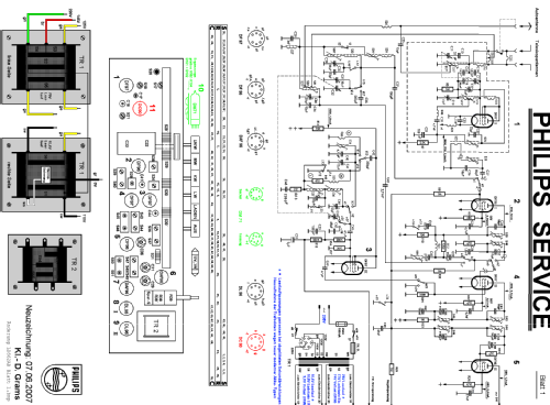
- die DM71 dient hier nicht als Abstimmanzeige, sondern wird als NF-Stufe zweckentfremdet. Das grüne Licht ist nur optischer Gag / Kontrolleuchte (?)
- Peso netto
- 8.2 kg / 18 lb 1 oz (18.062 lb)
- Prezzo nel primo anno
- 378.00 DM
- Fonte dei dati
- HdB d.Rdf-& Ferns-GrH 1956/57 / Radiokatalog Band 1, Ernst Erb
- Bibliografia
- HdB d.Rdf-& Ferns-GrH 1957/58
- Letteratura / Schemi (1)
- -- Original-techn. papers.
- Altri modelli
-
In questo link sono elencati 2549 modelli, di cui 2261 con immagini e 1566 con schemi.
Elenco delle radio e altri apparecchi della Philips Radios - Deutschland
Collezioni
Il modello Colette fa parte delle collezioni dei seguenti membri.
Discussioni nel forum su questo modello: Philips Radios -: Colette LD562AB
Argomenti: 9 | Articoli: 28
Uploaded to Schematics.
Print 100% at 300dpi on pastel shade paper to match.
30cm x 6.5cm. It doesn't matter if the very ends are clipped.
Stick with paper glue (UHU or Pritt Stick) and allow to dry before spraying with lacquer.
Michael Watterson, 03.Dec.13
Having studied the design we can start.
Make sure there is a DEAC replacement or at least a D cell. Also an nominal 90V HT battery or supply available. We won't try mains or just switch on.
Make sure there is a "plan" of what valves go in which socket. Don't assume existing chassis is correct.
The PSU is removed via three 3.5mm metric screws in the base. The main chassis slides out when the screws removed at each end. Also unscrew battery holder and DEAC retaining clip. Here I discuss on Cabinet Restoration fixing the battery holder and here at DEAC D6 model creating a working replica. This is needed for the mains power supply.
The valves are removed and pins washed with WD40, also the sockets. Filaments (pins 1 & 7) are tested with meter on 200 Ohms range. One DL96 has one 1/2 filament gone (O/C = Open circuit). Immediately I wonder are there leaky paper & foil capacitors to the grid? The Philips Annette is all ceramic capacitors for grid and screen grids.
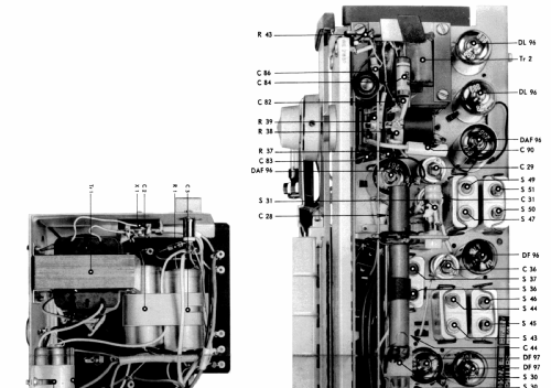
The schematic is examined and compared with the chassis. Note that the Bias decoupling capacitor and FM Discriminator are small electrolytic, 2uF and 5uF. Also note that both of these correctly have PLUS to chassis. One end seal is disintegrated on the C51 2uF Bias decoupler mounted under the 2 x DL96 between an chassis tag near DAF96 and a tag strip beside the DL96 (B9 and B10). Also I can see C91, C92 (B9 DL96 grid to B7 DAF91 anode and B10 DL96 grid to B8 DM71 anode) are paper 4n7F, not ceramic. I test one on the leakage tester and current is full scale > 50uA at 400V. A 100V ceramic 4n7F has zero leakage (needle doesn't move).
4 x 4n7F paper replaced
2 x 47 paper replaced
1 x 2uF Electrolytic replaced, one end cap open (C51 bias decouple)
Potentially problem capacitors
| Cx | Val | Test | Status | Rep? | Function |
| C51 | 2uF | Bad | Critical | Yes | Bias decoupling. Must be low leakage |
| C78 | 5uF | ? | no | Yes | FM discriminator. Lose FM |
| C91 | 4.7nf | Bad | Critical | Yes | anode to grid AC coupling |
| C92 | 4.7nf | Bad | Critical | Yes | anode to grid AC coupling |
| C85 | 4.7nf | Bad | Critical | Yes | anode to grid AC coupling |
| C85 | 47nF | Bad | no | Yes | g2 decoupling. Lose Gain |
| C69 | 47nF | Bad | no | Yes | AGC filter. Full RF/IF gain, no AGC |
| C84 | 4.7nF | Bad | ? | Yes | DAF96 grid to Volume pot. wiper |
| C62 | 4.7nF | ? | no | No | DF97 AM-Mixer/FM-IF2 g2 decouple |
| C52 | 4.7nF | ? | no | No | DF97 AM RF g2 decouple |
| C20 | 4.7nF | ? | no | No | VHF decouple |
| ? | ? | ? | ? | No | Various in PSU section |
If C51 has significant leakage then bias is reduced and DL96 Anode currents increase. If it's too large then the bias is too slow to reach desired value as source is 2 x 330K in series and grid "leak" 56 K of B4 DF97 local oscillator.
C62, C52 & C20 must be ceramic. All the paper & foil types replaced.
The set was powered of D cell and separate 90V pack that uses 60 x Alkaline AA cells in holders, but the two DL96 not installed.
Initially no filament power, but cleaning the switches fixed this.
HT current was nearly zero with no LT and with LT about 7mA on LW AM and 9.5mA on VHF-FM, which is reasonable. With both DL96 fitted there was 26mA. Massively too high! The schematic shows idle bias of 1mA screen grids and 2.6 mA x 2 for anodes, total 6.2mA, so total HT should be under 14mA on AM. (A typical AM only 4 valve battery portable is about 8mA to 12mA HT).
The DF97 B4 was replaced with one out of a box (If really NOS, I don't know). I will test some DF97 later. HT current now 16.5 mA LW (so 9.5 mA on output, if 1mA total g2, then 4.25mA per Anode, high but not a problem). On VHF-FM, 18.5mA. thus o/p anodes are then (18.5 - 9.5 - 1 )/2 = 4mA each.
Each DL96 was tried singly in each o/p socket. Only one socket was ging audio. The DM71 actually wasn't lit! Reseating the DM71 it lit and audio on both valves. The bias voltage vs Local Oscillator was plotted (see notes).
But the "Aus" (Off) selects MW. Why? because a secondary switch isn't moving. This is a common problem with the Annette and Colette in this era. Eventually after cleaning I found the dual shaft slightly bent. On straightening this the switch operated properly.
Then I added the replica DEAC and disconnected HT pack. I selected "Laden" (charge) with the replaced power cord plugged into shaver transformer for isolation (PSU & Chassis is loose on bench!).
The 12V 3W lamp glowed and the nearly flat NiMH gradually rose to about 1.38V. The HT battery connector had 104V (with no battery connnected). A small reviving current is passed to HT battery on "Charge" (Laden) via 4.7K ohms. This is less than 10mA peak into a 55V end-of-life pack and 1mA into a nealy fresh 90V battery. Thus Alkaline HT pack is best and AAA better than 10 x Alkaline PP3 (6 x AAAA internally rather than layers) as Alkaline will even recharge somewhat at low currents if only partially used.
The set works quite sensitive on VHF-FM and LW & MW. Sensitivity is poorer on SW. Actually the RF Preamp (FM IF 1) B2 isn't used on SW, no doubt the intention is a that a larger aerial is used? Perhaps intermodulation at the Mixer is a problem on SW where stations can be very strong with an aerial wire. The SW RF in is via centre tap on VHF choke at VHF Tuner input, so on SW only one rod needs to be extended, either one.
It certainly can go "loud".
Tweezers are needed with a large Magnifying Lamp to get in at and replace most of the capacitors.
Remaining issues:
- Battery operation is erratic. I'm not sure if it's the Battery pack or the switch. The mains plug must be inserted to activate a switch or the 90V HT battery isn't connected! At times perfect. On mains it's always fine.
- The VHF can be a bit distorted. Perhaps R34 2K preset balance for Discriminator needs adjusted.
- The bias voltage is low, and about 1/2 what it should be on Short wave (-4.5V gives class A, bias current slightly high!). This suggests the B4 DF97 isn't great. All components and voltages there check OK, as do the resistors and capacitors around DL96.
- The tone control is limited in operation, and tone a bit lacking in treble on VHF. Is there a leaky Paper cap I have missed?
- The switches have a tendency to fail to latch. They have to be pressed down quite hard. I can re-tension the latch bar spring at the "Aus" end and clean it all more, again!
Michael Watterson, 26.Nov.13
Philips Colette LD562AB Restoration Part 2: The Cabinet etc
The cabinet is in three main parts, a plywood main section with Bakelite front and rear panel. All is covered with a Rexine style cloth. Common problems are cracks to Bakelite, tears etc in cloth, damage to hinges, cracked / missing parts on plastic mounts for the aerials, broken ferrite rod, damaged telescopic aerials, corrosion to case or chassis parts from leaking D cell. The ferrite in my set is fine as are the hinges and door locks but all the other types of damage exist. The Annette uses a curved plastic scale which is often cracked, but the glass plate with two knob holes on the Colette seems more robust. Mine is fine.
Other cosmetic issues are paint missing from panel at controls and the speaker cloth is damaged/discoloured. The grill is also loose with most of the tabs missing. The screws mounting PSU are missing.
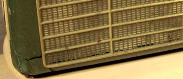
Broken Left corner (five parts but none missing!) and poor speaker cloth.

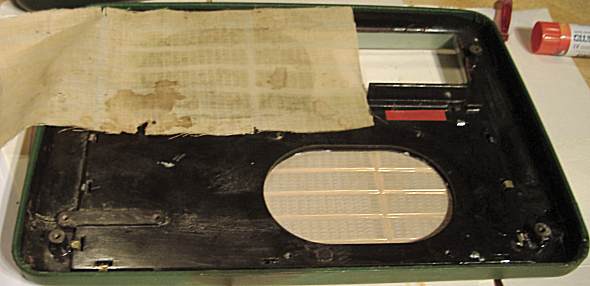
Hole in case above flap, damage to cloth.


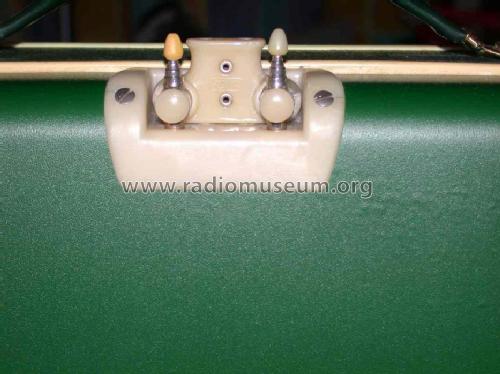
Bottom corner cracked off under cloth, Aerials and mount broken.

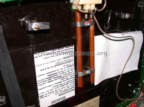
Corrosion in Battery area

Clip for "D" cells holder is scrap. wood corrodded badly at mounts.

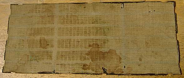
Cloth badly stained and damaged.

Nine tabs missing from speaker grill!
Removal of chassis from case.
Remove PSU (some slack on cable), brackets on dual D Cell holder, DEAC and aerial fittings. Two screws hold the main chassis which slides out. Unscrew loudspeaker. Four screws hold the front panel to the body of the case.
Bakelite Repairs
Tape over large holes at front with a tight piece of parcel tape and fill from rear with David's Isopon or other polyester based car body filler paste with catalyst. Not Fibre glass resin! On setting the tape peels off with a smooth surface,
Clean and dry cracked parts and check assembly order. Put superglue on both surfaces and allow to soak for a minute. Position parts lightly then breath on joint to make it damp and press hard. Hold for a minute or two. Superglue sets slowly on Bakelite with poor strength. Damp accelerates setting. After about 10 minutes mix two part epoxy and smear on inside in a thick layer, angle part so it collects most over the cracks. Perhaps use 10min type (but it's much less strong) and gently rock the part to distribute the resin for a few minutes. Any structural parts should use normal slow epoxy for best strength and be "keyed" with rough sandpaper. Surfaces must be very clean, dry and free of grease / oils / soap / white spirit etc.
Cloth should only be glued with PVA wood glue, PVA craft glue or "Pritt"/"UHU" paper glue sticks. Soaking rear with warm water for a few minutes helps. This advice is from a supplier (www ratchford . co.uk) who still make this kind of covering for cabinets, car panels as well as lighter materials for book binding.
Any holes or cracks in the covering are best filled with "knifing putty" sold for filling scratches and surface imperfections on car bodywork prior to re-spraying.

Super glue before Epoxy added.

Lever apart gently and a little superglue into crack.
(Apply Epoxy later)
Covering stuck down with PVA, Epoxy on inside (look bottom right) and inside of new speaker cloth.
Speaker Cloth & Grill
Various possible cloths are Linen or other Cross Stich cloth, Muslin, skirt / dress linings and nylon net curtains. In this case pure white nylon net curtain was the best match. It was dyed cream by scribbling all over with a pale brown "furniature" touch up marker and then wiping with a alcohol soaked tissue to smooth it out.
Pieces of coffee tin soldered to the grill to replace the missing tabs. Lightweight brass sheet might be more authentic. An SMD re-work hot air gun assisted the 25W soldering iron. Pre-tin and pre warm grill and tabs.

Torn cloth stuck, but it's very rough, so add knifing putty and rub down (dries fast)

Knifing putty on front.

Knifing putty on front.

Knifing putty on rear.

First coat of Artist's Acrylic paint applied over smoothed "knifing putty".
Batteries

Base springs off "996" packs dismembered for "F" cells to make AD4 packs.
Top connections cut from coffee tin.

Replica D6 pack containing NiMH Cell fitted (strap to be added). Made of Coffee tin!

Replica 90V HT pack (60 x AAA Alkaline cells) and new mains lead with Europlug.
Next the Electronics repair and restoration!
Michael Watterson, 24.Nov.13
Philips Colette LD562AB Restoration Part 1: Background
Also known as L5D62AB and UKW-Konzert-Koffersuper. Released in Germany 1955-1956 and in Netherlands as “Clipper” L5X62AB in 1956, though only the German model has “Colette” on the case.
Before commencing restoration the Electronics and to a lesser extent the Mechanics, case, covering, power etc must be understood.
Summary
- LW, MW, SW & VHF-FM
- Battery or Mains
- Tone control
- Economy Control
- Push Pull Audio out
- Car Aerial Socket
- External 6V LT charging (12V on Dutch models)
- Charge light
- Battery status display
- Year: 1956–1958
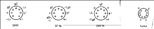
- Valves / Tubes 10: DF97 DF96 DF97 DF97 DM71 DF96 DAF96 DAF96 DL96 DL96
- IF 460/10700 kHz
Similar models to consider and contrast are the Philips Annette series UKW-Koffersuper LD452AB, LD462AB(Bakelite) LD471AB, LD480AB, L4D90AB (Dutch Regenboog LX4 or L4X series) and strangely the Vidor Vanguard. There are also related Scandinavian Dux AB57 and Dux AB58 which are like the Annette but add the Shortwave of Colette and use a DL94 (almost twice output power of DL96)
Philosophy
We have to decide if we are merely repairing or restoring. A contemporary professional service person wouldn’t generally modify a model unless parts where not available. “Bodgers” of course might even incorrectly modify a set to get it “going” with no consideration of longlivity, safety and quality. People restoring sets may want to only use original parts, or leave a model just for display rather than destroy the original. Others may use a modern part of the same value, but destroy the old part by stuffing inside it. Or perhaps leave the old part in place but out of circuit with the new part behind it. Or you may feel it’s acceptable on a 1950s model to simply fit replacement capacitors and resistors. Everyone seems to have different opinions on that.
I’m inclined to keep the original design and not add “improvements” such as DAB, USB, Earphone sockets, digital frequency counters, modern regulators, transistor replacements of valves, changes or enhancements in circuits UNLESS such a change was an official manufacturer’s modification in production or insisted on as field service change to solve a problem.
Similarly I prefer to try and restore the cabinet as it was, so no Danish Oil, Polyurethane or French Polish on Wood. Damaged fabric is a problem, but unless it’s completely unusable/scrap I put up with a foxed or scuffed appearance, perhaps touching up a bit.
Power Supply
In the USA and UK, usually Battery / Mains “tube”/”valve” models use a series filament chain. This simplifies Mains supply and ensures that if one filament fails the supply is removed from the rest. With Parallel filaments an unregulated supply will rise to a dangerous level for the remaining tubes, especially if the output tube fails. But in 1940 in Germany the Telefunken Y8 base tubes were optimised for NiCd (sold under DEAC brand) as each tube was different filament current so could not be operated in series. The advantage of the DEAC was two fold, that it acts as a parallel voltage regulator for Mains supply and then the LT cells which are consumed at perhaps x20 current of HT are an optional purchase.
No surprise that this didn’t catch on in the UK or USA where Setmakers either sold batteries or were originally only battery makers! Also the major UK market was for people that only bought one set, mains OR battery, depending on if they actually had mains electricity or not.
LT
So like many German and Philips Battery / Mains models the Mains PSU LT is regulated by a series dropper resistor and most important is the DEAC, an NiCd cell. With age these deteriorate and the voltage may rise to 2V or more. An actual NiCd of similar or a little higher capacity in a replica box is the best solution. A modern NiMH is however more readily available. The “C” size is about 3500mAH to 4000mA and “D” size (if not a “fake” with AA or C inside) about 7000mAH to 10000mAH. This must be very reliably connected to the terminals of the replica box as it limits the voltage. Many NiMH should not however be left indefinitely on charge. The other disadvantage compared to NiCd is that the average voltage is about 250mV higher. On charge with no load the cell will rise to 1.5V and on load fully charged is about 1.37V. If the optional D Cells are used these should not be left in the set as the NiMH will discharge them to about 50% if they are new. Alkaline are about x2 life than Zinc Carbon or Zinc Chloride in this application and less likely to leak. Interestingly the Alkaline will recharge somewhat in a Colette or Annette if no more than 2/3rds discharged. Any disposable cell must be removed before mains charging if exhausted or the NiMH will charge very slowly as most of the energy is wasted in the flat cells. Actually both the Annette series and this Colette put a very small current into the HT pack also. This would not really have charged the original “layercell” pack, but would have dramatically extended shelf life. It’s possible to fit 60 x AAA cells in an original size replica case, so these ideally should be Alkaline. The common practice of using 10 x PP3 (9V rectangular packs) is poor value, the Alkaline are not so much better than Zinc, because the Zinc layer cells fill the can but Alkaline uses 6 off AAAA cells, wasting space. The 60 off AAA pen cells will not mind the small HT current on mains and if less than 1/3rd discharged may actually recharge.
Grid Bias
Most Filament Tube battery sets after the use of grid batteries ceased use a resistor of 200 to 1000 ohms between LT- and HT- to provide grid bias of about -4V to -6V for the output tubes. This of course wastes HT voltage and power. It’s also less ideal for class AB or Class B outputs than Class A as the voltage is more variable and needs to be a higher drop. The solution on the Colette is to derive bias from the local Oscillator. At first sight this looks odd. The immediate thought would be a loosely coupled winding or sample anode and rectify it (there is an unused DAF96 diode). But actually the “solution” is simpler! With an oscillator biased by “grid leak” the grid will become negative. This voltage is simply filtered by a two stage RC filter 330K and 100pF followed by 330K and 2uF. Note that C51 2uF +ve pin thus goes to 0V.
On VHF-FM this oscillator is at a fixed frequency. On the AM bands the bias appears to vary somewhat between -5V and -8V depending on band and across the band. About -5V is really class A and about -8V is close to class B. If the voltage is only about -4.5V replace the DF97 assuming there are no leaky capacitors. If C51 2uF (Electrolytic) filter is leaky or if the audio feed capacitors C91, C92 (paper, so likely WILL be leaky) 4.7nF are leaky then the bias will be too poor and DL96 or Transformer damage can occur. See the next section. A compromise design of perhaps 150 Ohms in HT- for bias to limit current in event of B4 (DF97) failure might have been a better idea! Tthe DL96 grids are connected to 0V via effectively nearly 2.3 M Ohms grid leak (The 56K & 2 x 330K are shared) if the DF97 fails.
Architecture
Most Battery sets of this era use a DK96 (or possibly a DK92 for better Shortwave performance as it’s more similar to the 1L6 used in the Zenith Transoceanic). But here there isn’t one. This is why we mention the UK Vidor Vanguard, one of only two known UK tube portable with VHF-FM (the other is the Ever Ready Sky Emperor / BEREC Commander). Like the Colette, it has no Heptode/Pentagrid. Both sets use a Triodised Pentode as Local Oscillator and a Pentode as AM bands Mixer / RF amp. In both models the AM mixer Pentode is an ordinary FM IF stage for VHF. The Vanguard uses all DF97 and the triodised VHF Self mixing/ Oscillator is AM L.O. I have verified that the Annette LD480 and Vidor Vanguard do indeed work with a 50mA filament DC90 instead of 25mA filament Triodised DF97, one earth connection may need removed on socket, but this doesn’t seem to affect VHF operation. The LD452AB actually does use a DC90. Presumably it will work with a DF97. The Vanguard uses 3 x DF97 for FM IF and one of these is AM mixer. The IF and Mixer on it do also work with DF96, though it’s not quite the same pin connections or performance. It’s unclear why the 1st FM IF on the Colette, which is an RF preamp on AM bands is a DF96 rather than DF97.
|
|
Type |
AM |
FM |
Note |
|
B1 |
DF97 |
OFF |
Mixer/Osc |
Triodized |
|
B2 |
DF96 |
RF preamp |
1st FM IF |
|
|
B3 |
DF97 |
Mixer |
2nd FM IF |
Via g3, so DF96 won’t work! |
|
B4 |
DF97 |
Local Osc. |
fixed Osc. |
Triodized, generate grid bias |
|
B5 |
DF96 |
IF Amp |
3rd FM IF |
|
|
B6 |
DAF96 |
Det. AF Preamp |
AF Preamp |
Detector unused in FM mode |
|
B7 |
DAF96 |
AF Driver/Tone |
AF Driver/Tone |
Triodised. (Diode Unused) |
|
B8 |
DM71 |
Phase Inverter |
Phase Inverter |
Also Battery condition |
|
B9 |
DL96 |
AF Output |
AF Output |
Class AB push pull |
|
B10 |
DL96 |
AF Output |
AF Output |
Class AB push pull |
The DM71 isn’t a tuning indicator here (it usually is) but used as phase inverter to drive B10, the 2nd DL96. One can only suppose that either there wasn’t enough gain with B6 DAF96 on its own (and some passive tone control scheme) to use the 2nd DAF96 as a phase inverter as is done on several Ever Ready Table Models (Sky Monarch AM, Sky Monarch AM/FM, Spacemaster/BEREC Skyscraper Mk. II). Actually some reports (German) of DF64 used as phase inverter (sub-miniature hearing aid tube that can be wired under chassis). A DM160 couldn’t be used as it probably didn’t exist! But it seems to be not purely an indicator and phase inverter. As the bias is just a 390K resistor to OV, it does appear to vary length with LT condition. Just for comparison, the Ever Ready Sky Emperor (BEREC Commander) “solves” the running out of places to put tubes to drive the Push Pull output by reflexing the 1st FM IF (used just as Audio stage on AM) as gain -1 / Phase inverter to drive the 2nd DL96!
On FM the X3 and X4 germanium diodes are the FM discriminator. So C78 5uF +V pin goes to 0V.
On “Charge” (Laden), the charging current is via an under run 12V 3W lamp as a series dropper, this would be 48 Ohms with 12V on it, but there is rather less, so it may be about 40 Ohms. Current is also via 8.2 Ohms in circuit during mains operation too. In normal mains operation the 12V lamp is swapped for a 17 ohms resistor. LT would thus rise to over 10V without a load if there was no DEAC or NiMH cell across the LT supply. The schematic shows what looks like 9.5V on the bridge (presumably on normal operation as that is how the switches are drawn).
Next parts we look at the restoration and typical faults. Case Restoration.
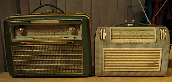
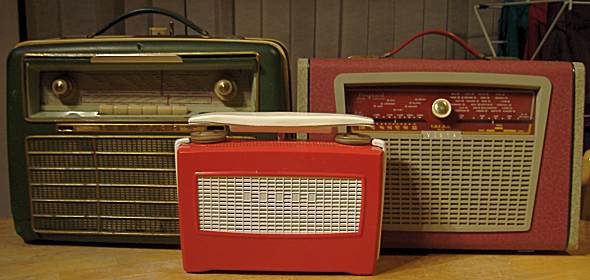
To give an idea of scale here is the Colette beside its sister Annette (LD480AB) and also the only UK portable tube model with LW, MW and VHF-FM, Vidor Vanguard (The Ever Ready/BEREC model has no LW, but SW instead). The small set is one of the last Vidor valve / tube models, with MW & LW only, the Vagabond. Both Vidor models are 1957.
Michael Watterson, 24.Nov.13
stolperte ich über ein Schaltungsdetail in der Endstufe.
Nachdem erste, allerdings verzerrte, Töne auf UKW zu hören waren, kontrollierte ich den Arbeitspunkt der Gegentacktendstufe. Am gemeinsamen Einspeisungspunkt der Gittervorspannung war dort jedoch keinerlei Spannung zu messen.
Bei der Verfolgung der Leitung landete ich nicht, wie erwartet, im Netzteil, sondern in der AM-Oszillatorstufe!
Nachdem das Studium der Schaltung die Richtigkeit dieser Überraschung bestätigte, wurde auch klar warum auf den AM-Bereichen überhaupt kein Empfang möglich war. Denn schließlich fehlte dort die Schwingspannung nicht nur für die Endstufe, sondern auch für die Mischstufe.
Die Ursache war schnell gefunden die zuständige Röhre (DF97 III) war defekt.
Nach kompletter Wiederherstellung des Gerätes war die Angelegenheit aber noch nicht erledigt.
Die Frage woher kommt denn eigentlich die Gittervorspannung beim FM-Empfang stellte sich zunächst?
Das Schaltbild gibt auf diese Frage beim näheren Hinsehen schon eine Auskunft.
Aber auch nach Klärung dieses Sachverhaltes bleibt immer noch ein Fragezeichen übrig.
Welchen tieferen Sinn hat diese immerhin eigenwille Schaltung überhaupt?
Franz Born
Allegati
- Endstufe (17 KB)
- AM-Oszillator (13 KB)
Franz Born †, 16.Jun.07
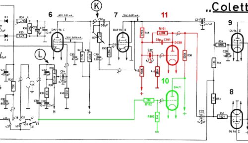
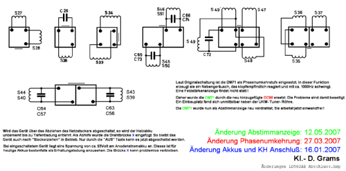
Nach meinem ersten Beitrag in diesem Forum wurde ich von einem namhaften Kenner der Materie kontaktiert. Es handelt sich um Herrn Darius aus Solingen, der den Beitrag hier im RM gefunden hat. Er teilte mir mit, dass die DM71 nicht optimal angeschlossen sei. Nur der Abgriff des Steuersignals an C78 Minus Seite sei richtig.
In der Tat hatte ich bereits festgestellt, dass bei meinem bisherigen Abgriff die max. Feldstärke im UKW Bereich etwas versetzt angezeigt wird. Bei dieser Anzeige war der Sender schon etwas zur hohen Frequenz hin verstimmt. So habe ich mich entschlossen, den Rat zu befolgen. Dabei ist es nun so, dass für AM unf FM je eine eigene Steuerspannung geschaltet werden muss. Die AM Anschaltung entspricht in etwa der bisherigen. Sie wurde am R29 abgegriffen. Die FM Anschaltung erfolgt wie gesagt am C78. R103 dient nur zur Potentialfestlegung des Steuergitters, wenn keine Steuerleitung ein Signal liefert.
Erste Tests ergaben nun, dass die Regelspannung am C78 sehr hoch ist. Bei starken Sendern wird die DM71 ganz ausgesteuert und erlischt. Aus diesem Grunde habe ich einen Spannungsteiler aus den Widerständen R102 und R104 vorgeschaltet. Damit arbeitet die DM71 im UKW Bereich optimal. Um nun die beiden Regelspannungen (AM und FM) zusammen zu führen, wurden die Dioden D101 und D102 erforderlich.
Alle zusätzlichen Bauteile habe ich auf einer kleinen Lochrasterplatine von 3 mal 3cm zusammengefasst. Diese Platine habe ich dann am Trägerblech der DM71 befestigt. So herrscht auch weiterhin Ordnung im Gerät.
Abschließend kann ich sagen, dass die DM71 sowie auch das gesamdte Gerät incl. auch der DC90 optimal funktioniert. Es macht einfach viel Spaß, es einzuschalten und zu nutzen.
Und nun viel Spaß beim Nachbau. Dazu möchte ich noch sagen, dass sowohl die DM70 / 71 als auch die DC90 heute noch erhältlich sind, und das für wenig Geld. Bei Rückfragen nutzen sie die registrierte Verbindung
Viele Grüße von hier aus Wuppertal und Solingen (die Klingenstadt)
Klaus- Dieter Grams CSD.Grams[A*T]t-online.de
Allegati
- neue Änderungsschaltung Teil1 (86 KB)
- neue Änderungsschaltung Teil2 (36 KB)
Klaus-Dieter Grams, 27.May.07
Hallo zusammen
Auch ich habe eine Colette aufgearbeitet und viel Zeit dafür investiert. Es hat viel Spass gemacht und es ist ein sehr schönes Stück herausgekommen, dem man die 50 Lebensjahre kaum ansieht. Doch zunächst zum Anfang:
Am Beginn der Arbeiten spielte das Gerät nicht. Der DEAC Akku war defekt und schloss die Heizspannung kurz. Der 90 Volt Akku fehlte. Nach Entfernen des Akkus waren erste Laute zu hören, jedoch mit starkem Brummen. So habe ich 6 Stck. Monozellen a´1,5 Volt parallel angeschlossen. Dadurch wurde das Brummen deutlich leiser. Zu guter letzt habe ich noch 2 * 4700µf angeschaltet. Danach war das Brummen weg. Bei dieser Schaltung beträgt die Heizspannung bei Netzbetrieb 1,57 Volt. Ein Wert, mit dem ich leben kann.
Als Ersatz für den 90 Volt Akku habe ich 10 Stck. 9 Volt Blockbatterien / Akkus eingesetzt. Damit ist ein Netz und Batteriebetrieb optimal ermöglicht. Doch nun fiel eine Besonderheit auf, die ich folgendermaßen gelößt habe: Wird das Gerät nicht über den Ausschalter abgeschaltet, sondern durch Herausziehen des Netzsteckers, kommt es zur Entladung des Heizakkus, weil dieser noch angeschaltet ist. Ein Zustand, der so nicht bleiben konnte. So habe ich den Kontakt, der normalerweise bei Batteriebetrieb durch das Einstecken des Netzsteckers in die Rückwand geschlossen wird, fest gebrückt. So "hängt" der 90 Volt Akku jetzt immer an der Ladeschaltung. Das kann auch ruhig so sein, den bei Netzbetrieb des Gerätes singt die Betriebsspannung des Netzteils etwas ab. Am Akku stehen dann 93 Volt an. Das ist gerade so viel, dass man von Erhaltungsladung sprechen kann. Eine Überladung findet nicht statt. Doch wird nun der Netzstecker bei laufendem Gerät gezogen, spielt das Gerät einfach auf Akkubetrieb weiter. Erst wenn die Aus- Taste betätigt wird, ist das Gerät auch aus. Damit ist das Problem gelößt.
Bei weiterer Durchsicht habe auch ich dann die üblichen Kondensatoren erneuert. Das war die gleich Aktion, die schon Herr Heigl beschrieben hat. Doch danach war bei sonst gutem Klang ein ca. 1000Hz Pfeifton zu hören, der sich immer weiter aufschaukelte. Es zeigte sich, dass die DM 71 zu einer Art Mikrofonie neigt. Klopft man gegen diese Röhre, so wird der Pfeifton lauter. So erneuerte ich die DM71. Doch auch mit der Neuen bestand das Problem fort. Das war auch der Augenblick, wo ich auf dieses Forum aufmerksam wurde und nach einer Lösung suchte. So habe ich alle Beiträge zum Thema DM 71 und deren Ersatz durch die DF 64 gelesen. Aber das mit der DF 64 gefiel mir auch nicht. So habe ich in meinen Röhrenhandbüchern nach geeigneten Alternativen gesucht und gefunden. Das Ergebnis sieht so aus:
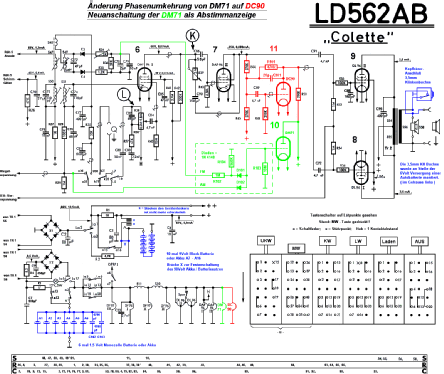
In das Gerät habe ich eine weitere Röhre des Typs DC 90 eingebaut und als Ersatz für die DM 71 angeschlossen. (siehe auch Schaltungsänderung, die ich als Foto zusammen mit weiteren Gerätefotos hochgeladen habe) Um die Ansteuerung der beiden DL 96 Gegenraktendstufen perfekt symetrisch zu gestalten, sind noch der Widerstand R101 und der Kondersatoer C101 als Gegenkopplung der DC 90 hinzugekommen. Damit ist das Problem gelößt und der Pfeifton beseitigt.
Mit Hilfe der Widerstände R102, R103 und R104 habe ich die DM 71 ihrer eigendlichen Bestimmung gemäß als Abstimmanzeige neu angeschlossen. Ich muß sagen, sie funktioniert so perfekt. Der dargestellte Strich verkürzt sich bei hoher Feldstärke und wird wieder länger bei schwachen Sendern.(siehe auch mein weiterer Beitrag zusammen mit aktualisiertem Schaltbild in Farbe, indem ich die DM 71 noch besser an die Regelspannungen für AM und FM angepasst habe.)
Zu guter Letzt habe ich den kratzenden Tastensatz, das Chassis und den Innenraum gründlich gereinigt. Jetzt sieht das Chassis aus wie gerade neu gefertigt und so spielt es auch, einfach sehr schön.
Als nächstes war nun das Gehäuse an der Reihe.
Zunächst wurde es komplett zerlegt. Alle Messingteile wurden aufpoliert und dann mit Klarlack (Plastic 70) versiegelt. Den Kunstlederbezug habe ich mit Autopolitur aufgemöbelt. Er sieht aus wie neu ! Einige kleinere Beschädigungen habe ich ausgespachtelt und dann gepinselt. Dabei war es mit viel Mühe verbunden, den richtigen Farbton zu treffen. Der hellblaue Bereich um die Skala herum war verkratzt. Diese Farbe habe ich in Matt mischen lassen und dann aufgetupft. So ergab sich eine Struktur wie bei dem Kunstleder. Es sieht wirklich sehr gut aus. Den Stoff hinter dem "Kühlergrill" habe ich erneuert. Zum Zusammenbau möchte ich noch sagen, dass ich Wert auf Servicefreundlichkeit lege. Daher wurden alle Module (Chassis, Netzteil, Akkusatz und Lautsprecher steckbar gemacht. Auf dem Innenraumfoto ist deutlich eine SUB-D 15pol. Steckverbindung zu erkennen. So lässt sich das Chassis leicht trennen. Steckt man dann ein 15pol. Computerkabel dazwischen, ist das Chassis außerhalb des Gehäuses in jeder Lage zugänglich und betriebsbereit. Ein Umstand, der beim Reinigen des Tastensatzes von großem Wert war.
Mit freundlichen Grüßen aus Wuppertal
Klaus- Dieter Grams
Breite des Beitrages editiert. Wolfgang Bauer
GR: Den grünen Rahmen eliminiert
Allegati
- Bilder meiner Colette (99 KB)
- Bilder meiner Colette Innenraum mit DC90 (146 KB)
- Die DC90 (118 KB)
Klaus-Dieter Grams, 26.Mar.07
Da ich in meinen ersten Berufsjahren in der hieseigen Philips-Service-Stelle mehrfach, genau nach schriftlicher Anleitung "derartige Basteleien" an noch fast fabrikneuen Geräten durchgeführt habe, kann ich etwas zur Aufklärung beitragen.
Da die Colette über eine Gegentalt-Endstufe (2 x DL96) mußte zu einer dieser Röhren eine Phasenumkehrung erfolgen. Diese Aufgabe übernahm, so auch im Schaltbild eingezeichnet, eine DM 71 !! Es handelt sich dabei um eine Miniatur Abstimmanzeigeröhre die aber lediglich sowas wie ein grünes Ausrufungszeichen erzeugt. Aber welches Röhrenkofferradio verfügte damals über ein " Magisches Band", das war schon etwas Besondereres.
Es stellte sich aber schon balb nach Erscheinen der Geräte heraus, diese Phasenumkehrfunktion mit der DM71 war nicht "das gelbe vom Ei".
Bei der Lösung dieser Angelegenheit ist das herausgekommen , was unser Sammlerkollege als Bastelei bezeichnete.
Da kein Platz für eine zusätzliche Röhre im Chassis vorhanden war, griff man auf die DF64 zurück. Bei dieser Röhre handelt es sich um kleines Bauteil ohne Sockel, Die Anschlußdrähte werden direkt in der Schaltung verlötet. Diese Bauweise wurde seinerzeit z.B. in Hörgeräten angewendet.
Die DM71 blieb im Gerät und bildete lediglich soetwas wie eine grüne Betriebsanzeige.
Leider hat diese Umbauanleitung, zumindestens bei mir, die 5 Jahrzehnte nicht überlebt. Es wäre schön, wenn sie doch irgentwo wieder auftauchen würde.
Allegati
- Phasenumkehrung mit DM71 (4 KB)
Franz Born †, 05.Oct.06
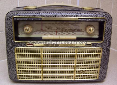
Vor einigen Wochen hatte ich bei ebay relativ günstig eine Colette ersteigert. Zustand: das Gehäuse (Überzug) hatte einige kleinere Beschädigungen und Verfärbungen, 1 Teleskopantenne war beschädigt. Der Portable gab keinen Ton von sich.
Als Erstes wurde aus dem Radio das Chassis und der Netzteil ausgebaut und untersucht. Die Netzsicherung war korrodiert und dadurch unterbrochen. Es hat sich auch herausgestellt, dass die Röhre DAF96 I mit einer Miniaturröhre DF64 auf der Chassisunterseite überbrückt war. Die DF64 war als Triode betrieben worden (Schirmgitter mit Anode verbunden). Ich vermutete, dass eventuell die DAF96 defekt war und deshalb durch die DF64 ersetzt wurde. Nun wurden die verdächtigen Kondensatoren, das waren 5 Stück ERO-Kondensatoren, C69, C85, C89, C91 und C92 mit dem Isotest überprüft und getauscht. Sie hatten alle Isolationswiderstände zwischen 1MΩ und 6MΩ. Der Elko C51 wurde ebenfalls getauscht. Auch die DF64 musste wieder raus. Dabei habe ich auch einen Verdrahtungsfehler gefunden, der bei dieser Bastelei passiert sein musste - eine Endstufe DL96 wurde nur schwach angesteuert und war beinahe wirkungslos. Bei einem ersten Probebetrieb spielte das Radio, jedoch mit Brumm. Ursache war der nicht angeschlossene DEAC-Akku. Der Akku ist natürlich unbrauchbar und wurde auch nicht mehr angeschlossen. Statt dessen wurde ein Elko 2200µF/16V zusätzlich eingebaut. Jetzt spielte das Radio wieder mit voller Leistung. Auch die DAF96 I war nicht defekt, Ursache für deren Nichtfunktion war der defekte Kondensator C85, der die Schirmgitterspannung faktisch kurzschloss. Die eingebauten Koppelkondensatoren C89, C91, C92 hatten 3 Anschlüsse (Schirm), wurden jedoch durch normale Kondesatoren ersetzt.
Jetzt wurde das Gehäuse in seine 3 Teile zerlegt und alle Ziergitter abgenommen. Beim Lautsprechergitter haben 2 Befestigungslaschen gefehlt, sie wurden durch 1,52 Cu-Draht ersetzt (eingelötet). Nun wurden die Gehäuseteile gründlich gereinigt, dabei stellte sich heraus, dass einige dunkle Flecken (grau bis schwarz) nicht mehr zu entfernen waren. Daher habe ich mich entschlossen das Gehäuse zu lackieren. Beim Farbenfachhändler wurde laut mitgebrachtem Muster ein passender Farbton gemischt und in eine Spraydose abgefüllt. Alle Gehäuseteile die nicht gespritzt werden durften, wurden mit Klebeband und Papier abgedeckt. Der Lack muss möglichst sparsam aufgetragen werden, damit die Struktur der Oberfläche nicht verloren geht. Leider habe ich einen Fehler begangen, der Lack wurde "Halbglanz" geordert, "Matt" wäre richtig gewesen. Die Klappe vor der Skala wurde nicht gespritzt, wegen dem Colette-Schriftzug. Der Lautsprecherstoff hinter dem Ziergitter war ebenfalls fleckig und wurde auch sparsam gespritzt - sieht aus wie neu. Jetzt muss noch die Teleskopantenne repariert werden, aber das ist ein anderes Kapitel: Antennenreparatur.
Bilder sind beim Modell hochgeladen.
Gerhard Heigl, 04.Oct.06