
EM84

|
|
||||||||||||||||||||||||||||||||||||


|
Hits: 351 Replies: 0
Precise dB Monitoring with Eye Tubes
|
|||||||||||||||||||||||||||||||||||||||||||||||||||||||||||||||||||||||||||||||||||||||
|
Joe Sousa
08.Sep.24 |
1
Fellow radiophiles, I present here an article I published in 2006 in audioXpress magazine. In this article I explore the dB characteristic of the electronic beam deflection in eye tubes. This is to say that the beam deflection is proportional to the log of the input voltage. This is particularly well suited to monitor signal strength in a tube radio receiver as well as the audio level in a tube tape recorder. The last generation of these tubes includes the EM84, which displays a dynamic range of 30dB and is perhaps the best eye tube ever made. In my effort to measure the log-conformity of the beam deflection, I created an electronic voltage step scale that is calibrated in equal dB increments on the phosphor target. I later combined this dB-step electronic scale with the usual input signal to the tube to view the beam deflection on the target in steps of 3dB, 6dB or 10dB, over a 30dB range. Click any image to enlarge in a separate window Tuning Eye TubesTuning eye tubes came into use before the Second World War to help tune radio receivers by indicating signal strength. This was helpful to reduce distortion and adjacent channel interference that would result if the radio were tuned too far from the center of the channel. The eye tubes were developed as a cheaper alternative to needle movement meters. The green glow of a eye tube was also an atractive feature on the radio dial. It was not until the 1960's that d'Arsonval needle movements were made economically enough in Japan to displace indicator tubes and they used very little power in the then new transistor radios. During the decades from the 1930's to the 1960's, when tuning indicator tubes were in production, they found wide use in instrumentation as a low cost alternative to the needle meter movements. Capacitor measurement bridges and tube testers were among the more common instruments making use of these inexpensive indicator tubes.
At full signal strength, the two rectangles meet in the center, forming a solid rectangle 1.5 inches long. The following diagram shows the internal arrangement of the EM84/6FG6. These tubes were built with two integrated sections sharing a common cathode.
The data sheets from various manufacturers show a carefully designed transfer curve from the input voltage at the internal triode grid to the size of the gap between the two glowing rectangles. This curve follows a logarithmic characteristic very closely, covering 30dB of input voltage range. This accurate decibel response and the large bright display made these tubes suitable for use as fast, precise indicators of recording levels in tape recorders of the 1950's and 1960's. The logarithmic characteristic was also a benefit for use in radio tuning service, as it permitted extended indication of tuning at lower signal levels. Creating Decibel Steps
Several adjustments are possible to make this graduated pattern fill the fluorescent target exactly. First, in the standard EM84 wiring diagram above, the 250V supply voltage or the value of the 470K pull up resistor can be adjusted to get the two fluorescent bars to meet exactly at the center when the maximum negative level of -22V or more is achieved and the input triode is cut-off. You can adjust the 470k pull up from 200K to 1Meg to make the rectangles overlap slightly in a bright line at the center, or you can leave a slight gap, to suit your preference. The following schematic shows the constructed dB step generator and was also simulated in LTspice.
The start of the deflection can be adjusted, so that the target is nearly completely blank when there is no input signal. The trimpot RU11 injects a variable offset voltage between -1V and 1V, into the circtuit path to the triode grid. The node LOGSTEPS drives the EM84 triode grid. The last adjustment to be made to accommodate variations from tube to tube and supply voltage variations is the maximum deflection into the center of the target. Here, you simply need to adjust the gain of the circuit driving the input grid with the RU6 pot, so that the maximum level of the dB step sequence makes the step pattern close precisely at the center. As mentioned above the 470k triode anode load at the EM84 also affects the closed bar behaviour. Both the offset, gain and 470k pull may need to be readjusted for best uniformity in the dB steps. Once the tube is calibrated for the starting and ending points of the pattern, we can configure the step size. The size of the dB step can be calibrated for any step size inside the 30dB range of the tube fluorescent target. I chose three switchable step sizes of 3dB, 6dB and 10dB. These step sizes are selected by a 3 position selector switch on the left side of the schematic diagram, and are calibrated individually with an oscilloscope. The fixed dB step sequence is created with an exponential step sequence, where each step is a fixed percentage of the previous step. The circuit generates the exponential step sequence at LOGSTEPS to drive the input grid of the tuning eye tube. I used a simple method to obtain this sequence by sampling the exponentially decaying voltage of a precharged RC network. 555 timer U1 tells the LF398 sample-and-hold IC to sample the continuous exponential decay of C3 at fixed intervals, every few milliseconds as seen on the pulse train and exponential decay in the following figures. This method is very convenient, because all the steps decay by the same number of dB with each new sample, and are adjusted as a group, simply by adjusting the sample rate, which is to say the frequency of 555 timer U1. The dB step selector switch simply connects different adjustable timing resistors to this 555 timer U1.
The dB selector switch selects between three preadjusted timing resistors of the first 555 timer U2 to sample the decaying exponential voltage on C3 more frequently for small dB steps, or less frequently for large dB steps. Compare the figures on the right.
The following describes the calibration method for the dB step sizeFor the 3dB step, adjust RU10 trim pot to get steps that are 70.7% of the voltage of the previous step. For the 6dB steps, adjust RU7 with a slower step rate to get each new step at 50% of the previous step, and for 10dB steps, slow down the step rate with RU8 to obtain steps that are only 31.6% of the previous step. This is best done with an oscilloscope, but you can make these adjustments using the EM84 by applying known DC voltages with these dB ratios, and then adjusting the the timing resistors for 555 timer U1 until the step size shows the same deflection as the known DC voltages. Displaying dB steps on different phosphor target shapesThe dB step generator is useful to check various indicator tube types, and to compare various tubes of the same type from different manufacturers or different levels of wear. Tube types, like the classic round eye 6U5/1629, the bathtub target EM80/EM81/EM85, or the off-center round fan deflection EM71, have a logarithmic deflection characteristic, but the smaller deflection area makes them harder to read. The logarithmic range is also smaller in the round eye tubes, down to only 15dB, as compared to 30dB for the EM84. See the table at the end of this section with measured results of their display range in dB. The UM4 has opposing target deflection areas with different sensitivities. The photo shows a higher sensitivity target above and the lower sensitivity target below. The first photo on the left with 0V applied to the UM4 is rotated 90o with respect to the two following photos with 6dB steps. Each deflection area only spans 15dB, but the lower area starts deflecting when the upper area is nearly fully deflected. The upper area responds to weaker signals.
The dark portions of the concave targets tend to show some reflected glow. As a result, concave metal targets offer a lower contrast than the phosphor targets that are painted on the glass. In this group of round eye tubes, the EM71 is the most suitable with its wide deflection area and about 25dB of deflection range. The EAM86 has a rectangular side view pattern like the EM84, and the deflection is horizontal rather than vertical. The EM800 shown below is the only eye tube I have found with a linear deflection scale, which makes it unsuitable for use with the dB step generator. It is pin-compatible with the EM84, and the deflection pattern is only one single bar that covers a target area similar to the EM84. The EM800 requires a 200k plate load on the triode.
The EM801 is a variant of the EM84 that shows two identical channels on the same phosphor target. It has two rectangular patterns adjacent to each other, but they are narrower, slightly distorted and are harder to read. The input to the right stripe in the photo was left floating. The EMM803 has two independent and dissimilar target deflection areas. The longer deflection area is logarithmic and very similar to the target of the EM84. The shorter deflection area is linear and extends no more than 1/4inch, just below the main target. This small target area could be used as a multiplex FM stereo indicator. This particular EMM803 shows phosphor burn in the dark bands on the target. The 6AL7 tube requires about -10V to +20V applied to its deflection inputs, and it does not include a triode preamplifier. It also has a blurry beam and short deflection, which makes it impossible to discern any step pattern. The deflection response is fairly linear, which makes it unsuitable for use with the log step generator. Summary of measured eye tube characteristics
Adding the VU meter function
One display mode, shown on the right, adds graduated dB steps to the otherwise smooth, green rectangles that show the VU level. The other display mode, shown below adds The equal dB steps make it easy to measure the strength of the signal in dB or volts, accurately (V=10^dBV/20). The first mode, with stepped bars over a dark background, is generated when the peak detected VU signal on C1 in the schematic below combines with precision exponential voltage steps from FIXEDSTEPS in U2 and U3 to limit the maximum negative voltage excursion at MODSTEPS to the peak negative value on C1. MODSTEPS drives the grid amplifier in the first schematic above. The first figure to the right shows the truncated exponential staircase, with the zero value up one division from the center and the max negative swing at the center line, so that only two steps occur. Note that this negative value is the detected peak negative VU value, not just the normal step value. As the VU value grows more negative with more signal, the bottom step grows until the next dB step appears below and starts to grow too. The two steps in the scope photo appear as two steps that modulate the brightness of the bars in the photo to the right. Alternatively, flipping the display mode switch that swaps the polarity of D3 and D4, causes the opposite voltage limiting effect in U2 and U3, where the exponential voltage now has a positive upper limit as seen in the wide step in the second photo. In this mode, there is a permanent dB pattern on the entire phosphor lenght that gets partially covered by the solid bars that indicate the VU level. This results in a display of smooth VU bars over a graduated dB step background.
The VU circuit just above generates the VU signal with a peak detector and a calibrated attenuator to obtain full scale ranges of: -10dBV=316mVpeak 0dBV=1Vpeak +10dBV=3.16Vpeak +20dBV=10Vpeak +30dBV=31.6Vpeak +40dBV=100Vpeak These voltages can be DC or peak levels and close the bars fully at the center. If you want to use this circuit to monitor maximum power at speaker terminals, you can monitor the power of amplifiers ranging from 12mW peak into 8 Ohms with the -10dBV range, as may be the case with a headphone signal, to 1250W peak into 8 Ohms with the +40dBV scale. The decay rate of the VU detector can also be set with R4, to 6dB/sec for careful monitoring of maximum swings with a slow meter decay, or 6dB/150ms do gauge the dynamic behavior of the sound material. Using the eye tube VU meterI have found the 6dB step setting most useful to monitor dynamic content in music. The higher resolution of the 3db step is best suited to check frequency response in an amplifier or speaker system. The 10dB step setting has been handy to check the total dynamic range of EM84 tubes. One possible setting that can be useful in recording or precise monitoring of maximum signal levels, is to adjust step size to obtain just one or two steps for comparison with the incoming VU signal. In the case of a recording level meter, you would accomplish this by adjusting the indicator gain to obtain maximum deflection for a +3dB maximum record level. Then, you could adjust the next step to 70.7% of this level, for 0dB. Finally, lower the value of R4 in the first schematic to shorten the period of the second 555 timer U2 to shorten the step sequence to just these two steps. This way, you can see very precisely when the 0dB level is exceeded, without any parallax error caused by external bezel markings. In this application, the preferred mode is the smooth VU bars over a graduated background. Another advantage of combining dB step levels with the signal voltage is that the VU voltage will always be accurately measured with respect to the dB step graduation, even with a change of tubes, or when supply variations affect the deflection factor of the tube. When you change tubes, or as the tube ages, you simply readjust the high voltage amplifier gain with RU6 in the first schematic to make the green bars meet precisely in the center and readjust the offset control to minimize deflection with zero input and good dB step conformity at the ends of the deflection target. These adjustments will not affect the relationship between the VU signal and the graduated dB steps, so that measurement accuracy is preserved. The nature of dB measurements is such that two stepped dB VU meters could be driven by the same audio signal with their two input attenuators set 30dB apart, such that the combined dB measurement range of the two tubes would be doubled from 30dB to 60dB. For example, if one VU meter is set to 0dBV full scale, it will indicate sound peaks from -30dBV (0.032V) up to 0dBV (1V), then another unit could measure the same audio signal with it's input attenuator set to +30dBV, so that it can monitor signals from 0dBV (1V) to +30dBV (32V). This expanded dynamic range of 60dB is particularly useful to monitor classical music, where the quiet passages are often more than 30dB quieter than the loudest musical peaks. The VU meter circuit in the second schematic includes D5 biased with -5V to limit the output drive when the input is overdriven, but the -10dBV range should not see input signals greater than 5V to avoid damage to the input stage. As an afterthought, you could add 10k in series with pin 3 of U1 to extend protection in the -10dBV range. But R14=1k could still be damaged with gross voltage overdrive. Not all EM84 tubes are created equalThis shows 9 different samples of EM84, all operating in the same conditions. All tubes were driven with 6dB steps, except for tube 1, 4 and 9, which were driven with 10dB steps. All photos were taken with the same fixed manual exposure, so that you can compare the relative brightness among tubes.
There is a great variation in brightness and phosphor smoothness. The gaps at the center of some of these tubes can be eliminated with a slight increase in input voltage amplitude. The start of the pattern at the ends of the phosphor target on tube 4 could be evened out with the offset adjust knob. All tubes were able to display the full 30dB range with very good accuracy. The quality and smoothness of the phosphor target makes some tubes better than others. The brightest tubes were the Telefunken (1), Russian (2) and Zenith (5). The Russian tubes had a somewhat rough target, but were still quite usable. Some house brand tubes like the RWN-NEWHAUS and WEBCOR, were barely usable, with a dim and rough phosphor target. The last tube 9 by Sylvania shows phosphor burn bands which tend to make the dB steps confusing to read. The constructed project in two sections with the dB VU meter and the basic eye tube power and test fixture. (Click photos to enlarge)
The dBuino - PCB Construction
He kindly gave me a set of boards and parts. My favorite mode to use my pair of EM84 is to set one attenuator to -10dBV full scale and the other to +20dBV full scale, as shown in the photos, while using the internal microphone, although external stereo input is available with the mini phone jack. In this mode, the total range for the pair is 60dB. When the eye on the right closes fully with -10dBV=316mVpeak, the eye on the left starts to respond to the input and closes fully with 20dBV=10Vpeak. These voltages are calibrated for external inputs. The internal microphone is not calibrated for sound pressure level, so this is only a relative measurement. This setting is very effective to monitor any sound level without attenuator adjustment and to listen to classical music with its very wide dynamic range. I glued strips of green transparent plastic on the phosphor screens to enhance display contrast. The contrast is increased because all external light other than green is blocked, and any external green light that shines on the white phosphor screen is attenuated twice, once into the target and once again on the way back out. The green light produced by the phosphor is attenuated only once on the way out. For green light, this is a 2x increase in display contrast, which is increased further by blocking out all other external light colors.
The following PDF links show the schematics and PC boards in the freeware PCB layout tool KiCad. Click dbuino_schematic_precise_db_monitor_with_em84.pdf, with the two channels and power supply. Click dbuino_pcb_layout_preamp_modulator_dbstep_generator_em84.pdf. Clcik dbuino_pcb_layout_power_supply.pdf. Click dbuino_screen_shots.pdf to see 3D views of the project and PCB layers in KiCad. The two bills of materials for the two boards include references to parts suppliers: Click bill of materials eyetube_io_board.xls Click bill of materials eyetube_power_board.xls The layout of the two PC boards is shared without cost at oshpark by Steve Martin under user name Xenomorph. You can order your own boards from oshpark: Click "dBuino Power Board" or search oshpark for this board name. Click "dBuino Eyetube IO Board" or search oshpark for this board name. Thank you very much Steve, for creating and sharing these board layouts without cost. It was a fun collaboration and resulted in a very practical implementation! For more on eye tubes see Lighting up Dark Eye Tubes. Regards, -Joe
|
||||||||||||||||||||||||||||||||||||||||||||||||||||||||||||||||||||||||||||||||||||||


|
Hits: 2716 Replies: 1
EM84 ohne Getterspiegel
|
|||||||||||||||||||||||||||||||||||||
|
Gerhard Eisenbarth
03.Oct.17 |
1
EM84-Typen aus meiner Sammlung ohne von außen sichtbarem Getter
Auf einigen Typen steht als Herstellerland: Made in Holland. Bedeutung der Philips Codierung: VS = EM84 2 = zweite Produktion L = Produktionsstätte Mazda, Belgien Das Zeichen in der Codierung der 2. Code-Zeile (RCA und S) ist ein offener Kreis mit einem Punkt im Zentrum und deutet auf die Produktionsstätte Elektronski Industija, Nis, Yugoslavia Die restlichen Zeichen betreffen den Produktionszeitpunkt, die ich aber nicht interpretieren kann. Kann jemand helfen, der sich mit den Philips-Codierungen auskennt? Untersuchung einer EM84 ohne GetterspiegelFast unbemerkt wurde vermutlich ab 1955 eine Getterentwicklung eingeführt, die zu keinen sichtbaren Getterspiegeln innerhalb von Röhren führte. Auffällig für mich ist das Magische Band, Typ EM84. Hier tauchten Ende der 60er Jahre des vorigen Jahrhunderts Versionen auf, bei denen weder ein Getter noch ein Getterspiegel sichtbar ist. In anderen Rundfunkröhren ohne Getterspiegel ist wenigstens eine von außen sichtbare Anordnung vorhanden, die auf einen Getterkörper hinweist. Um zu ergründen, auf welche Weise das Vakuum erhalten bleibt ohne sichtbare Getter oder Getterspuren, habe ich mich entschlossen, das Innenleben einer intakten EM84 diesbezüglich zu untersuchen. Dazu musste die Röhre geöffnet werden. Philips Codierung: VS2 L413 VS = Typ EM84, 2 = zweite Produktion, L = Produktionsstätte Mazda, Belgien, 413 = Produktionszeitpunkt ???
Detailansichten vom vorgefundenen Gasbinder. Weil der gasbindende Stoff nicht verdampft wird wie ein Getter sondern Gasreste an sich bindet, wird im Folgenden das Gebilde als „Gasbinder“ bezeichnet.
Der Gasbinder ist auf dem Bodenblech des Blendenkastens mit vier Punktschweißungen befestigt.
Detailaufnahme vom Gasbinder
Detail der Ausbuchtung für die Gasbinder-Pille Der Gasbinderbehälter besteht aus mit Löchern bzw. Schlitzen versehenem dünnem Blech. Die Außenabmessungen betragen 10 mm x 5 mm. Die Gasbinder-Pille hat einen Durchmesser von 4 mm und eine Dicke von ca. 0,5 mm. Die Gasbinder-Pille ist sichtbar porös. Der Gasbinderbehälter ist auf dem Bodenblech des Blendenkastens mit vier Punktschweißungen verbunden. Durch die Schlitze kann die Gasbinder-Pille Gasreste aufnehmen.
Die Gasbinder-Pille aus der geöffneten EM84 hat einen Anteil Kohle bzw. Graphit. Dies deutet auf eine Zusammensetzung nach Siemens Patenten. Die Gasbinder-Pille hinterlässt Spuren auf Papier wie von einem weichen Bleistift. Die Ausgestaltung des Gasbinders beschreibt das Siemens Patent DE 2062992: "Die Erfindung betrifft einen Getterkörper zum Betrieb bei Raumtemperatur in elektrischen Entladungsgefäßen, bei dem die Gettersubstanz zum Befestigen an Systemteilen oder sonstigen Teilen des Entladungsgefäßes, z.B. in einem Blechbehälter untergebracht ist …. ….. daß die Gettersubstanz aus einem Gemisch vom nichtverdampfenden Getterstoff Zirkon mit etwa 30 Gew. % Graphit (Kohle) als hochporös gesintertes Getter-Sinterteil zum Anbringen an beliebiger Stelle im elektrischen Entladungsgefäß als Getterkörper ohne Heizvorrichtung in einem vorwiegend offenen Molybdän-Blech- oder Kohlebehälter untergebracht ist. "
Im Patent sind mit neun Figuren mögliche Gasbindermontagen dargestellt. Die Fig. 1 zeigt das Prinzip des Gasbinderaufbaus, wie er in der EM84 verwendet ist, ein Gasbinderbehälter (1) in dem das Gasbinder-Sinterteil (2) eingepresst ist.
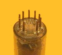
Eine Besonderheit zeigt das obige Foto. Bei allen EM84 Typen in meiner Sammlung ohne Getterspiegel erfolgt die Kontaktierung zum leitenden, durchsichtigen Innenbelag über zwei Federbleche. |
||||||||||||||||||||||||||||||||||||
|
Jacob Roschy
06.Oct.17 |
2
4 weitere EM84 ohne Getterspiegel fand ich in meinem Bestand. Obwohl von verschiedenen Marken, sind sie sind alle exakt baugleich, soweit erkennbar, genau wie das Exemplar im Bild unten in Post 1 von Herrn Eisenbarth.
eine ist von der Marke „555“ mit dem Code VS2 L5D4, eine ist von der Marke „Adzam“ mit dem Code VS2 L1G (ohne Bild hier)
2 Stück sind von Lorenz, eine mit dem Code VS2 Ͼ6D*, bei der anderen ist nur Ͼ6D* sichtbar. VS = EM84 *das Zeichen Ͼ ist tatsächlich um 90° gedreht, mit der Öffnung des Kreises nach unten. „Adzam“ ist die Röhrenmarke der belgischen Firma M.B.L.E. und nicht Mazda, wie in der Philips-Codeliste angegeben. Dafür ist Mazda-France in der Liste nicht erwähnt, obwohl diese einen riesigen Marktanteil hatte; möglicherweise wird sie dort zu C.I.F.T.E. gezählt. Eine weitere EM84 von „555“ hat einen oberen Getterteller, ist ansonsten baugleich mit den anderen und hat den kaum sichtbaren Code D5J2. M. f. G. J. R. |
||||||||||||||||||||||||||||||||||||
 Die geöffnete Röhre. Blick durch die Blendenöffnung in den Blendenkasten
 Blick durch die Blendenöffnung auf den Gasbinder


 Gasbinderbehälter mit Gasbinder-Pille
 Gasbinder-Pille


|
Hits: 6952 Replies: 0
EM84 (EM84)
|
|
|
Vincent de Franco
05.May.07 |
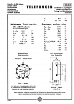
1 Avec une tension de 250V et une charge de 470k ohm, 0 à -22V de tension sur la grille permet de faire varier la taille de la barre d'affichage de 0 à 21mm. Une caractéristique de gain variable permet en plus d'améliorer la sensibilité pour les signaux plus faibles. |
End of forum contributions about this tube
| Data Compliance | More Information |