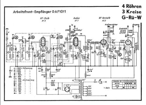
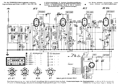
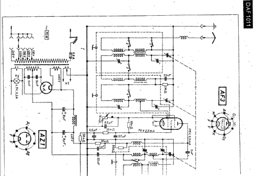
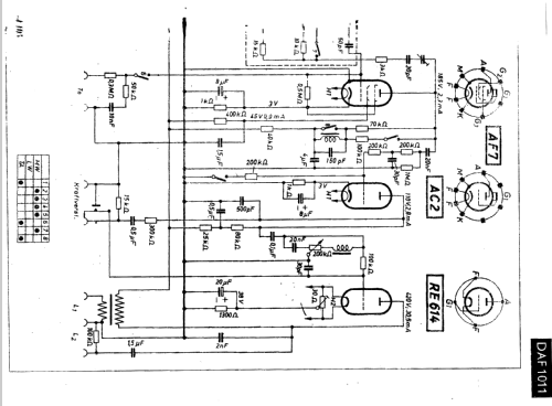
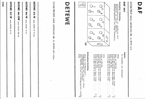
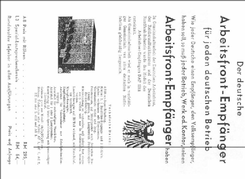
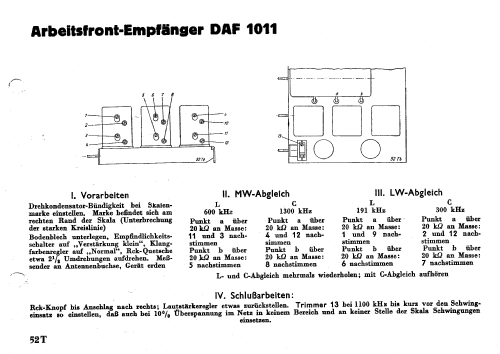
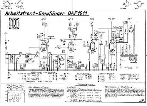
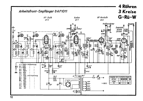
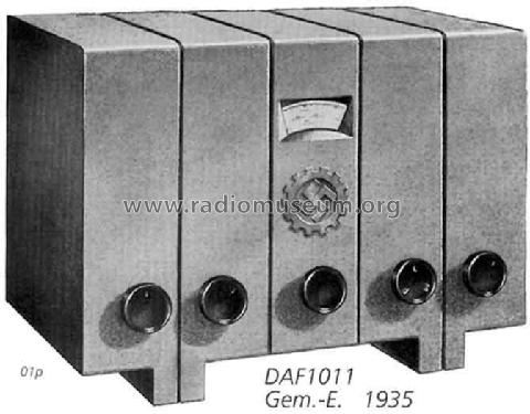
Arbeitsfront-Empfänger DAF1011
Gemeinschaftserzeugnisse Vorkrieg
- Paese
- Germania
- Produttore / Marca
- Gemeinschaftserzeugnisse Vorkrieg
- Anno
- 1935–1939

- Categoria
- Radio (o sintonizzatore del dopoguerra WW2)
- Radiomuseum.org ID
- 14731


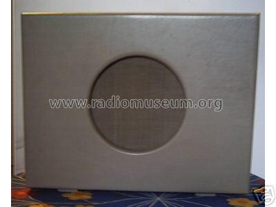
zugehöriger Kontrollautsprecher. Ebay-Bild.


Aus "Sürag", Programmzeitschrift von 1939
Clicca sulla miniatura dello schema per richiederlo come documento gratuito.
- Numero di tubi
- 5
- Principio generale
- A reazione (con rigenerazione); 1 Specialità; 2 Stadi BF
- N. di circuiti accordati
- 3 Circuiti Mod. Amp. (AM)
- Gamme d'onda
- Onde medie (OM) e onde lunghe (OL).
- Tensioni di funzionamento
- Alimentazione a corrente alternata (CA) / 110-240 Volt
- Altoparlante
- - Questo apparecchio richiede altoparlante/i esterno/i.
- Materiali
- Mobile di metallo
- Radiomuseum.org
- Modello: Arbeitsfront-Empfänger DAF1011 - Gemeinschaftserzeugnisse
- Forma
- Soprammobile basso, con andamento orizzontale (grosse dimensioni).
- Dimensioni (LxAxP)
- 397 x 255 x 237 mm / 15.6 x 10 x 9.3 inch
- Annotazioni
- Arbeitsfront-Empfänger. Wellenbereiche: 198...555 m; 910...2000 m. Ausgang für Lautsprecher: 200 bis 6000 Ohm. Leistungsbedarf bei 220 Volt: 60 Watt. Beleuchtungslampe: 4,5 V/0,3 A. Tonblende-Regler.
Nach Anfangspreis (1936/37) kostete das Gerät 1938/39 nur noch RM 270.- (kpl.m.Röhren).
Eine Auflistung aller deutschen Hersteller ist hier zu finden.
- Peso netto
- 12.8 kg / 28 lb 3.1 oz (28.194 lb)
- Prezzo nel primo anno
- 295.00 RM !
- Fonte esterna dei dati
- E. Erb 3-907007-36-0
- Fonte dei dati
- HandB.d.d.Rundfunk-Handels 1936/37 / Radiokatalog Band 2, Ernst Erb
- Riferimenti schemi
- Schenk-Regelien und FS-Bestückungstab.
- Bibliografia
- Funkgeschichte der GFGF (9495)
- Bibliografia immagini
- Das Modell ist im «Radiokatalog» (Erb) abgebildet.
- Altri modelli
-
In questo link sono elencati 59 modelli, di cui 47 con immagini e 37 con schemi.
Elenco delle radio e altri apparecchi della Gemeinschaftserzeugnisse Vorkrieg
Collezioni
Il modello Arbeitsfront-Empfänger fa parte delle collezioni dei seguenti membri.
Musei
Il modello Arbeitsfront-Empfänger può essere visto nei seguenti musei.
Discussioni nel forum su questo modello: Gemeinschaftserzeugn: Arbeitsfront-Empfänger DAF1011
Argomenti: 10 | Articoli: 35
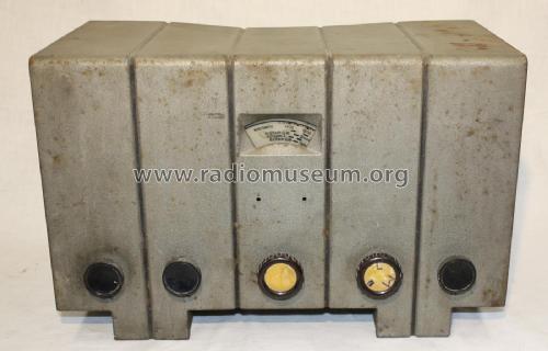
Die Lackierung eines DAF kann durchaus mit Hammerschlaglack aus dem Baumarkt erfolgen. Er muss dabei jedoch dünn aufgetragen werden, so bleibt die Kräusellackstruktur erhalten. Das Ergebnis sieht allerdings etwas heller aus als im Original. Möglicherweise ist aber der Altlack in der Regel auch verschmutzt bzw. nachgedunkelt. Stellen, die keinen Originallack und deshalb auch keine Struktur mehr hatten, wurden glatt belassen, was kaum auffällt. Siehe auch hier.
Der nachlackierte DAF, deutlich ist die Kräusellackstruktur zu sehen:

Viel Spass bein Restaurieren!
Ralf Keil
Ralf Keil, 23.Nov.09
I'm selecting new capacitors to replace the block electrolytics in my DAF. One of the schematics I have lists two separate voltage ratings for them: Arbeitspannung (which I assume means "working voltage") and "Pruefspannung" which is much higher. For example, the 0.5 uF preamp coupling capacitor no. 97 on the AC2 plate has a listed working voltage of 400 v. but a Pruefspannung of 1500 v.! I can't even find capacitors rated that high. What does this number mean? I have a 0.47 uF capacitor rated 630 v. Is there some reason I should not use that? Thanks!
Michele Denber, 30.Aug.09
Hallo,
habe einen DAF1011, dessen Farbe noch echt sein dürfte. Leider müßte diese ausgebessert werden.
Hierzu habe ich einen Bekannten, der Modellbauer ist, befragt. Er meinte, die sehr rauhe Struktur der Farbe ist nicht einfach herzustellen. Selbst die Farbe ist seiner Meinung nach zweischichtig ausgeführt.
Bevor er jetzt mit Marmorlack und ähnlichem Experimentiert, würde mich interessieren, wie der Farbaufbau tatsächlich gemacht wurde und evtl. gibt es ja auch Tipps aus der Neuzeit.
Einfach silberne Farbe auftragen ist aus meiner Sicht nicht korrekt.
Viele Grüße
Klaus Bayer
Allegati
- Farbe (120 KB)
Klaus Bayer, 12.Aug.09
Sorry for the blank message. The Editor was not giving me a text window. I thought maybe it was waiting for me to hit Return in the Title field, but all that did was post a blank message. I don't know why it was doing that. Now it seems to be working.
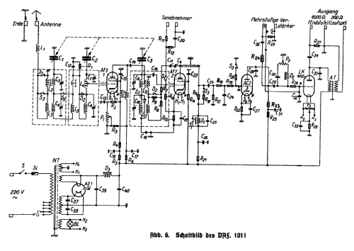
Anyway, I am now replacing the second block capacitor in my DAF-1011, part no. 6766, the 1.5uF/4uF block located on the bottom of the chassis in the middle. This block has three leads: black, yellow, and green. The black lead is ground. I'm now stuck figuring out where the remaining two go. The green lead measures lower, so I'm calling that the 1.5 uF wire, making the yellow wire the 4 uF section. The green wire connects to a 400K resistor as you can see here:

But I only see one 1.5 uF electrolytic capacitor in the schematic (coming off the plate of the RE614, below) and it connects to a 0.1M resistor!

The 4 uF side does connect to a resistor, but it's shown as a 40K.

In my radio, you can clearly see this is a 400K. So now I'm really wondering what's going on here. Is my assumption of which wire is which wrong? I know the capacitor is bad, so perhaps it's turning up bad readings on my meter. Or maybe the schematic is wrong? Or maybe I'm looking at the wrong parts in the schematic? Can someone please help? Thanks / danke sehr!
Michele Denber, 01.Dec.08
Now that I have removed the insides from my block capacitor, I need to figure out the best way to put the new ones inside the empty shell of the original. There's plenty of room since the old one measures 3.5" x 2.5" x 4" (9 x 6.5 x 10.4 cm). The new capacitors only measure 1 5/8" x 1" x 1 7/16" (4 x 2.7 x 3.5 cm) each. Does anyone have a good idea of how to secure the two new capacitors? I could:
1. glue them to the inside of the original shell,
2. make a bracket to fit inside the shell and mount them to that,
3. just let them lie loose,
4. melt new wax and embed them in that, or perhaps something better that I have not thought of. Has anyone else done this? What would you recommend? Any help would be appreciated. Thanks / danke / merci.
Michele Denber, 18.Sep.08
Michele Denber, 12.Jan.08
Hallo!
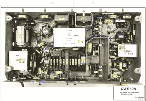
Suche einige Fotos von der Chassisunterseite.
Es soll einigermassen historisch wieder hergestellt werden.
Besonders die Blockkondensatoren wären mir wichtig.
Auf dem Bild ist es ja nicht besonders "restauriert", oder?
Allegati
- daf-chassis (143 KB)
Ralf Keil, 27.Sep.07
Hallo,
habe gestern (siehe Thread Schaub Bristol von mir) ein DAF-Chassis gefunden, eingebaut im Bristol.
Heute habe ich nach längerem intensivem Suchen im kompletten Haus des Verkäufers im Keller das Gehäuse gefunden.
Das Emblem vorne fehlt, weis jemand, ob es davon Nachfertigungen gibt?
Da das Gehäuse ziemlich angerostet ist, würde ich es gerne neu lackieren lassen. Hat jemand Erfahrung damit und kann mir sagen, wie man dies am Besten macht und mit welcher Farbe?
Vielen Dank und herzliche Grüße
MiJo
Michael John, 08.Jun.07
habe hier das Unterteil des Lautsprechergehäuses da.
Es fehlt die Abdeckung des Lautsprechers selbst (auch "Laterne" genannt).
Ich möchte die Abdeckung ergänzen, bei Bedarf im Selbstbau.
Kann mir jemand die Maße für die Abdeckung von seinem Modell abnehmen ?
Gibt es evtl. noch Bilder für den Aufbau im Inneren, vorallem um den Lautsprecher herum ?
Danke schon mal
Klaus Bayer
Klaus Bayer, 25.Jan.05
Gruß
Dirk Becker
Dirk Becker, 22.Nov.03